Accelerator pedal control device of intelligent vehicle

An accelerator pedal, intelligent vehicle technology, applied in the layout of the power unit control mechanism, vehicle components, transportation and packaging, etc., can solve problems such as intelligent control failure

Inactive Publication Date: 2015-04-08
赵天水
7 Cites 0 Cited by

AI-Extracted Technical Summary

Problems solved by technology

[0003] However, due to the conflict between the control of the intelligent automatic control drive device and the manual operation device, in th...

Method used

[0014] According to an embodiment, a smart vehicle accelerator pedal control device includes: a pedal lever 1 and a pedal surface 3 fixedly connected thereto, a driving device, and an installation fixture 18, wherein the driving device is used to drive the pedal lever 1 And the pedal plate surface 3 fixedly connected with it pivots, and the pedal rod 1 is provided with an elastic return element to automatically return to the state where the vehicle does not accelerate when the accelerator pedal is released without being operated; the installation and fixing device is used to fix the drive device. On the vehicle, the drive device includes: a pedal deck clamp, a telescopic lifting mechanism and a horizontal push mechanism, wherein the pedal deck clamp is hinged to one end of the push arm link 7, and the push arm link 7 The other end of the...

Abstract

Disclosed is an accelerator pedal control device of an intelligent vehicle. The control deice comprises a pedal rod (1), a pedal plate face (3), a driving device and a mounting fixing device (18); and the pedal plate face, the driving device and the mounting fixing device are fixedly connected with the pedal rod. The driving device is used for driving the pedal rod (1) and the pedal plate face (3) fixedly connected with the pedal rod to rotate in a pivoting manner; the pedal rod (1) is provided with an elastic reset element, and therefore when an accelerator pedal is released, and is not operated, the pedal rod is automatically reset to be in the automobile non-accelerating state; and the mounting fixing device is used for enabling the driving device to be fixedly arranged on the vehicle.

Application Domain

Propulsion unit arrangements

Technology Topic

Automotive engineering

Image

  • Accelerator pedal control device of intelligent vehicle
  • Accelerator pedal control device of intelligent vehicle
  • Accelerator pedal control device of intelligent vehicle

Examples

  • Experimental program(1)

Example Embodiment

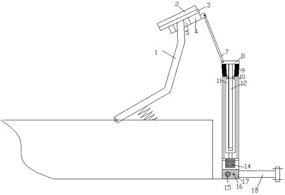
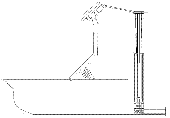
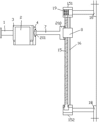
[0013] Combine below Figure 1-4 The present invention will be described in detail.
[0014] According to an embodiment, an intelligent vehicle accelerator pedal control device includes: a pedal lever 1 and a pedal plate surface 3 fixed thereto, a driving device, and an installation fixing device 18, wherein the driving device is used to drive the pedal lever 1 and to fix it. The connected pedal panel 3 pivots, and the pedal lever 1 is provided with an elastic return element to automatically return to the state of the vehicle not accelerating when the accelerator pedal is released and not operated; the installation fixing device is used to fix the driving device on the vehicle , The driving device includes: a pedal board clamp, a telescopic lifting mechanism and a horizontal pushing mechanism, wherein the pedal board clamp is hinged to one end of the push arm link 7, and the other end of the push arm link 7 It is hinged to the upper side of the drive plate 8 of the telescopic lifting mechanism. The telescopic lifting mechanism further includes a telescopic drive motor 14. The telescopic drive motor 14 is mounted on the sliding seat 17 and is dynamically connected to the threaded sleeve 11. The upper end of the telescopic stud 12 is fixedly connected with the drive plate 8 and the outer peripheral surface of the telescopic stud 12 is also provided with a longitudinally extending sliding guide groove. The sliding seat 17 is also fixedly connected with a sliding guide Sleeve 10, the sliding guide sleeve 10 is provided with engagement teeth that are slidably fitted with the sliding guide groove; the lower side of the drive plate 8 and the upper end of the sliding guide sleeve 10 are also connected with The telescopic shield 9 protects the telescopic stud 12 from external pollution;
[0015] The horizontal pushing mechanism includes a horizontal drive motor 19 mounted on the first seat body 151. The horizontal drive motor 19 is dynamically connected with one end of the horizontal drive screw 15 and the other end of the horizontal drive screw 15 is supported on the second seat 150 through a bearing. A guide rod 16 is also fixedly connected between the first seat body 151 and the second seat body 150. The sliding seat 17 is provided with a threaded hole that is threadedly matched with the horizontal drive screw 15 and slides with the guide rod 16. The matched guide holes are thus supported on the horizontal drive screw 15 and the guide rod 16; the first seat body 151 and the second seat body 150 are respectively fixedly connected to the installation fixing device 18; Both ends of the push arm link 7 have a double-lug 200, 201-type pushing wall structure, and the concave portion between the lugs of the double-lug structure is used to cooperate with the lugs of the hinged object. Both the lugs of the ear-shaped structure and the lugs of the hinged object are provided with light holes for the hinge shaft to pass through;
[0016] Thus, when the pedal board surface clamps clamp the pedal board surface 3, the lowering of the telescopic stud 12 can drive the accelerator pedal to pivot to increase the vehicle acceleration, and the rising of the telescopic stud 12 can drive the accelerator pedal Pivoting to reduce the acceleration of the vehicle. When emergency braking is required, the horizontal drive motor 19 can drive the horizontal drive screw 15 to rotate so that the telescopic lifting mechanism can move horizontally, so that the pedal is driven by the push arm link 7 The board surface clamping member quickly releases the clamping of the pedal board surface 3 to release the accelerator pedal, and the accelerator pedal quickly returns to the non-accelerating state of the vehicle under the action of the elastic return element.
[0017] In one embodiment, the thread lead of the horizontal drive screw 15 is greater than the thread lead of the telescopic stud 12.
[0018] In one embodiment, the pedal board clamping member is in a form in which the upper and lower clamping members 2, 4 are elastically hinged to each other, and the lower clamping member has a slot 5 for receiving the driving pedal rod 1.

PUM

no PUM

Description & Claims & Application Information

We can also present the details of the Description, Claims and Application information to help users get a comprehensive understanding of the technical details of the patent, such as background art, summary of invention, brief description of drawings, description of embodiments, and other original content. On the other hand, users can also determine the specific scope of protection of the technology through the list of claims; as well as understand the changes in the life cycle of the technology with the presentation of the patent timeline. Login to view more.
Why Eureka
Try Eureka