Lifting platform with automatic moving rail

A lifting platform and self-propelled technology, which is applied in the field of elevators, can solve the problem of not being able to cross a higher height, and achieve the effect of convenient operation and flexible movement

Inactive Publication Date: 2015-04-08
济南华北升降平台制造有限公司
View PDF6 Cites 4 Cited by
  • Summary
  • Abstract
  • Description
  • Claims
  • Application Information

AI Technical Summary

Problems solved by technology

[0003] The purpose of the present invention is to provide a self-propelled rail lifting platform, which is used to solve the problem that the existing mobile scissor lift cannot span a higher height and move on a fixed rail

Method used


Image

  • Lifting platform with automatic moving rail
  • Lifting platform with automatic moving rail
  • Lifting platform with automatic moving rail

Examples


Embodiment Construction

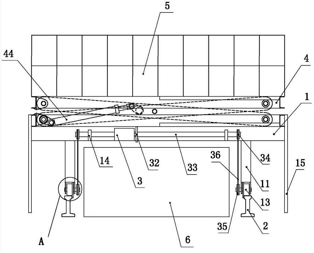
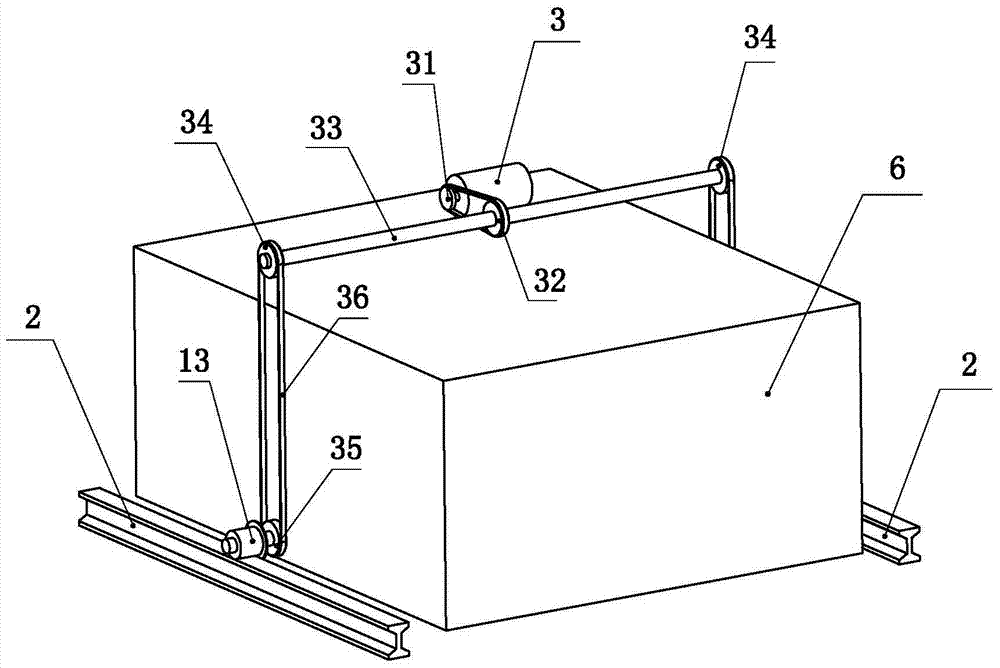
[0021] Such as Figure 1 to Figure 5 Shown, the present invention comprises base 1, supporting leg 11, track wheel shaft 12, track wheel 13, protective plate 15, track 2, motor 3, driving sprocket 31, driven sprocket 32, rotating shaft 33, upper sprocket 34, Lower sprocket 35, top plate 4, first support rod 42, second support rod 43, oil cylinder 44, roller 45 and guardrail 5, the present invention is described below in conjunction with accompanying drawing.

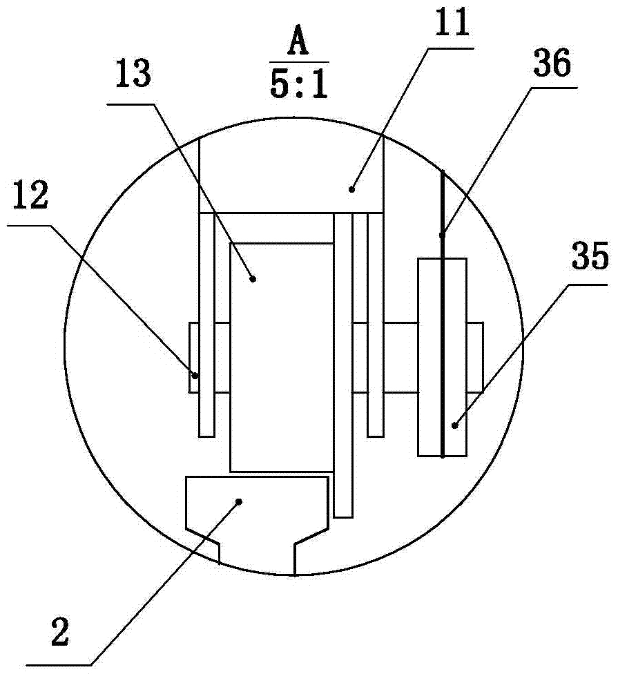
[0022] Such as figure 1 As shown, the base 1 is a profile weldment, and four vertically placed legs 11 are fixed on the bottom of the base. The height of the legs should ensure that the bottom of the base is higher than the height of the driving end 6. The drive head is a part of the fixed production line in the workshop. Four legs surround a square, and a track axle 12 is installed at the bottom of each leg, as figure 2 As shown, a track wheel 13 is fixedly installed on the track wheel shaft, and the track wheel is ...


PUM


Abstract

The invention provides a lifting platform with an automatic moving rail, and relates the technical field of lifting machines. The lifting platform with the automatic moving rail is used for solving the problems that an existing moving shear-folk lifting machine cannot span higher height and move on a fixed rail. For the lifting platform with the automatic moving rail, which is provided with the invention, the lifting part comprises a base, a first supporting rod and a second supporting rod which are arranged in an X shape, and a top board which is arranged at the tops of the two supporting rods, supporting legs are arranged at the bottom of the base, rail wheels are respectively arranged at the lower parts of the supporting legs, and the rail wheels can roll on the rail which is laid on the ground so as to drive the lifting part to move. A motor and a transmission mechanism are arranged on the base so as to transmit the rotary motion of the motor to the rail wheels. A guarding fence is arranged on the top board so as to protect operators. The lifting platform with the automatic moving rail, which is provided by the invention, can move forwards and backwards according to the production procedures of products, is flexible to move, and is convenient to operate.

Description

technical field [0001] The invention relates to the technical field of lifts, in particular to a lift platform that can walk along a certain track. Background technique [0002] There are many types of lifts, among which the scissor lift is the most common one. Its scissor-type mechanical structure makes the lift have higher stability and greater carrying capacity after it is lifted. However, in the assembly process of some large-scale products (such as containers), it is required that the elevator can cross the active end (the driving head of the automatic conveyor chain) with a certain height and place the product on the automatic conveyor chain. Existing mobile lifts cannot meet this requirement. Therefore, there is an urgent need for a lift that can cross the higher active end and move linearly on a fixed track to meet the needs of the workshop when processing products and improve production efficiency. Contents of the invention [0003] The object of the present inv...

Claims


Application Information

Patent Timeline
IPC IPC(8): B66F7/08
CPCB66F7/08
Inventor 罗殿华罗佃全李培军
Owner 济南华北升降平台制造有限公司
Why Eureka
Try Eureka