Device and method for monitoring vertical deformation of hydraulic construction

A technology for hydraulic structures and monitoring devices, applied in measurement devices, optical devices, height/level measurement, etc., can solve problems such as difficulty in circuit setting, construction and layout, monitoring of uneven settlement, etc., to reduce engineering monitoring and The effect of testing cost, convenient project transportation and use, convenient installation, inspection and maintenance

Active Publication Date: 2015-04-08
HOHAI UNIV
View PDF5 Cites 9 Cited by
  • Summary
  • Abstract
  • Description
  • Claims
  • Application Information

AI Technical Summary

Problems solved by technology

[0003] At present, conventional settlement monitoring devices have many shortcomings such as difficult construction and layout, low reusability, difficult maintenance, poor durability, low precision, and susceptibility to electromagnetic environment interference.
Optical fiber sensors have the characteristics of radiation resistance and corrosion resistance, and have obvious advantages in the monitoring of uneven settlement diseases; but from the current situation of optical fiber deformation monitoring, distributed real-time monitoring methods are current research and application hotspots, but the technology itself and engineering The practicability is not yet mature, especially for the application of optical fiber loops for settlement monitoring.
By using the changes of Rayleigh scattering, Fresnel reflection and Brillouin scattering in the optical fiber, not only can the uneven settlement disease be accurately located theoretically, bu

Method used


Image

  • Device and method for monitoring vertical deformation of hydraulic construction
  • Device and method for monitoring vertical deformation of hydraulic construction
  • Device and method for monitoring vertical deformation of hydraulic construction

Examples


Embodiment Construction

[0025] The present invention will be further described below in conjunction with the accompanying drawings.

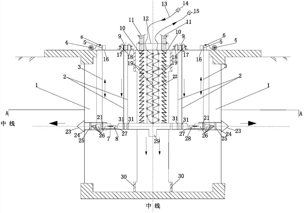
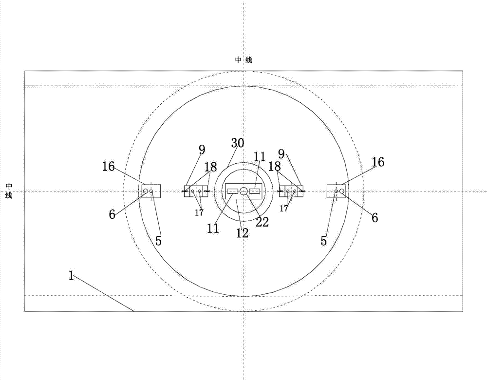
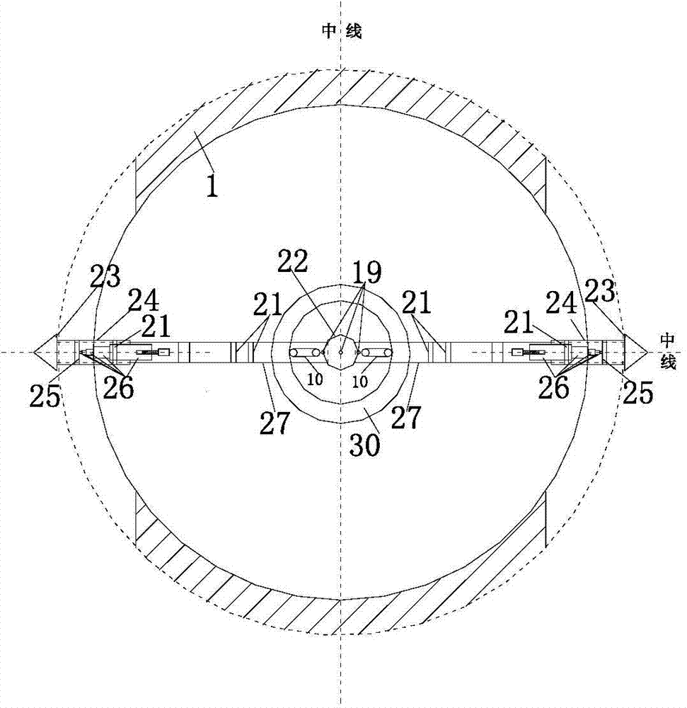
[0026] like Figure 1 to Figure 6As shown, a vertical deformation monitoring device for a hydraulic structure of the present invention includes a bottom-through shaft 1 located in the earth-rock joint area, an inner tube 30 located inside the bottom-through shaft 1, and the bottom-through shaft 1 is provided with lugs, Hanging on the earth-rock joint area through the lugs, a displacement platform 27 is installed in the inner tube 30 of the carrier, and the two sides of the displacement platform 27 are symmetrically installed with a drive motor 8, and the drive motor 8 is installed on the displacement platform through a bracket. 27, the drive motor 8 is connected with the drive shaft 7, the drive shaft 7 is provided with external threads, the drive shaft 7 is inserted into the five-stage piston 26, the five-stage piston 26 is provided with internal threads that cooperat...


PUM


Abstract

The invention discloses a device and a method for monitoring the vertical deformation of a hydraulic construction. The device comprises a bottom-through shaft and an inner carrying tube positioned inside the bottom-through shaft, wherein a displacement station is arranged in the inner carrying tube; drive motors are symmetrically arranged on two sides of the displacement station, and are connected with a conical drill by virtue of a five-stage piston; piston shells on two sides are respectively connected with lifting devices which are used for promoting motion of the piston shells; correcting devices which are used for correcting level of the displacement station are symmetrically arranged at two ends of the displacement station; the middle part of the displacement station is connected with one end of a group of symmetrically arranged springs, and the other end of each spring is hinged with a vertical measuring tape; an optical fiber hanging drum is arranged between two springs, and is filled with a corrugated loop optical fiber; and an optical fiber buckle is arranged on the corrugated loop optical fiber. The device has the advantages of use repeatability, convenience in assembly, real-time detection and maintenance and the like, and has the characteristics of distribution type, micro-macro structure, real-time performance, high adaptability to complex environment and the like.

Description

technical field [0001] The invention relates to a vertical deformation monitoring device and a monitoring method of a hydraulic structure, belonging to the construction field. Background technique [0002] The soil-rock bonded areas in hydraulic structures such as embankments and sluices often have uneven settlement during operation, which has adverse effects on the safety and normal use of buildings, and even leads to building damage or accidents. By arranging monitoring instruments or devices in the soil-rock combination area, real-time acquisition of regional settlement information, reasonable analysis of the spatial and temporal variation of regional settlement, timely detection of abnormal conditions of regional settlement (especially uneven settlement), and scientifically taking preventive or control measures, It is of great significance to ensure the safe service of hydraulic structures. [0003] At present, conventional settlement monitoring devices have many shortc...

Claims


Application Information

Patent Timeline
IPC IPC(8): G01C5/00
CPCG01B11/18G01C5/00
Inventor 苏怀智杨孟韩彰田始光李金友
Owner HOHAI UNIV
Why Eureka
Try Eureka