
Ultra-precision drive device based on electromagnetic-permanent magnet drive

A technology of permanent magnet drive and drive device, which is applied to piezoelectric effect/electrostrictive or magnetostrictive motors, generators/motors, electrical components, etc., which can solve problems such as drive errors and failure to truly meet requirements, and achieve Effects of controlling deformation, improving drive control accuracy, and strengthening magnetic field strength

Active Publication Date: 2018-01-19
SHANGHAI JIAO TONG UNIV
View PDF6 Cites 0 Cited by
  • Summary
  • Abstract
  • Description
  • Claims
  • Application Information

AI Technical Summary

Problems solved by technology

[0004] For the above-mentioned existing precision displacement driver, since the magnetic field generated by the electromagnetic drive device affects the deformation of the sensitive material, the sensitive material must be arranged in the magnetic circuit generated by the energization of the electromagnetic drive device; heat will be generated after the electromagnetic drive device is energized, and the sensitive material Under the effect of heat, it will have a certain thermal expansion, and for the precision displacement driver, a small amount of variation will cause the drive to produce errors, which cannot really meet the requirements of modern enterprises for precision drives.

Method used


Image

  • Ultra-precision drive device based on electromagnetic-permanent magnet drive
  • Ultra-precision drive device based on electromagnetic-permanent magnet drive
  • Ultra-precision drive device based on electromagnetic-permanent magnet drive

Examples


Embodiment 1

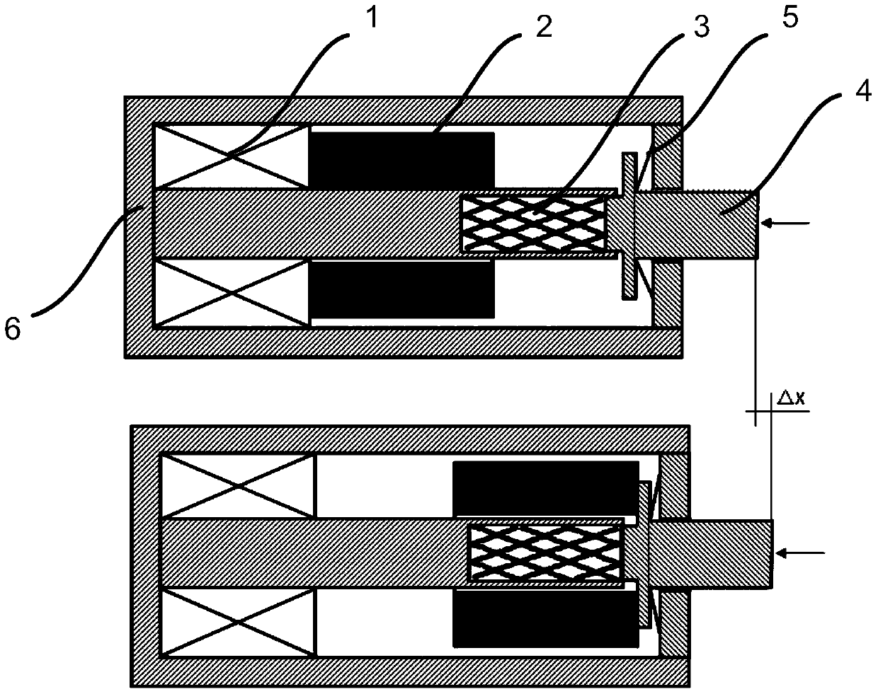
[0049] Such as figure 1 As shown, this embodiment provides an ultra-precision drive device based on electromagnetic-permanent magnet drive, including: an electromagnetic drive mechanism, a displacement drive mechanism, and a displacement output mechanism, wherein the displacement drive mechanism is arranged under the control of the electromagnetic drive mechanism In the magnetic field, the displacement drive mechanism is deformed under the control magnetic field of the electromagnetic drive mechanism, and the displacement output mechanism is connected to the deformation output end of the displacement drive mechanism;

[0050] The electromagnetic drive mechanism includes: a permanent magnet driver and a permanent magnet; the permanent magnet forms a relative movement with the displacement drive mechanism under the action of the permanent magnet driver, and then forms a changing magnetic field force to make the displacement drive The mechanism is located in the magnetic circuit ...

Embodiment 2

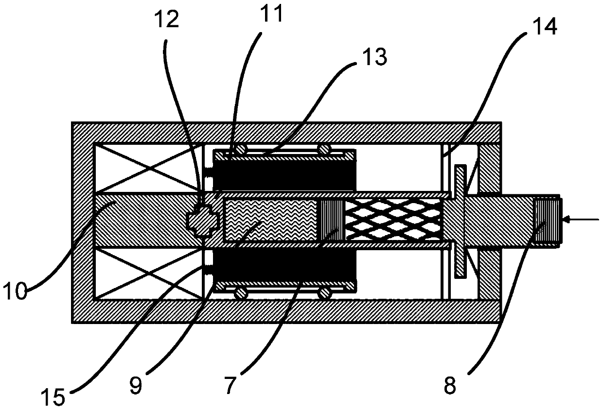
[0063] Embodiment 2 is a preferred example of Embodiment 1. On the basis of the technical solution of Embodiment 1, by adding corresponding components, the ultra-precision drive device based on electromagnetic-permanent magnet drive provided by Embodiment 1 can achieve more and more performance. .

[0064] The ultra-precision driving device based on electromagnetic-permanent magnet drive provided in this embodiment, on the basis of Embodiment 1, also includes any one or more of the following components:

[0065] - a reed, the reed is arranged between the displacement output mechanism and the magnetostrictive rod;

[0066] - an inner piezoelectric material body, the inner piezoelectric material body is arranged at the inner end of the magnetostrictive rod, and has an interaction force with the magnetostrictive rod;

[0067] - an outer piezoelectric material body, the outer piezoelectric material body is arranged at the displacement output end of the displacement output mechani...

Embodiment 3

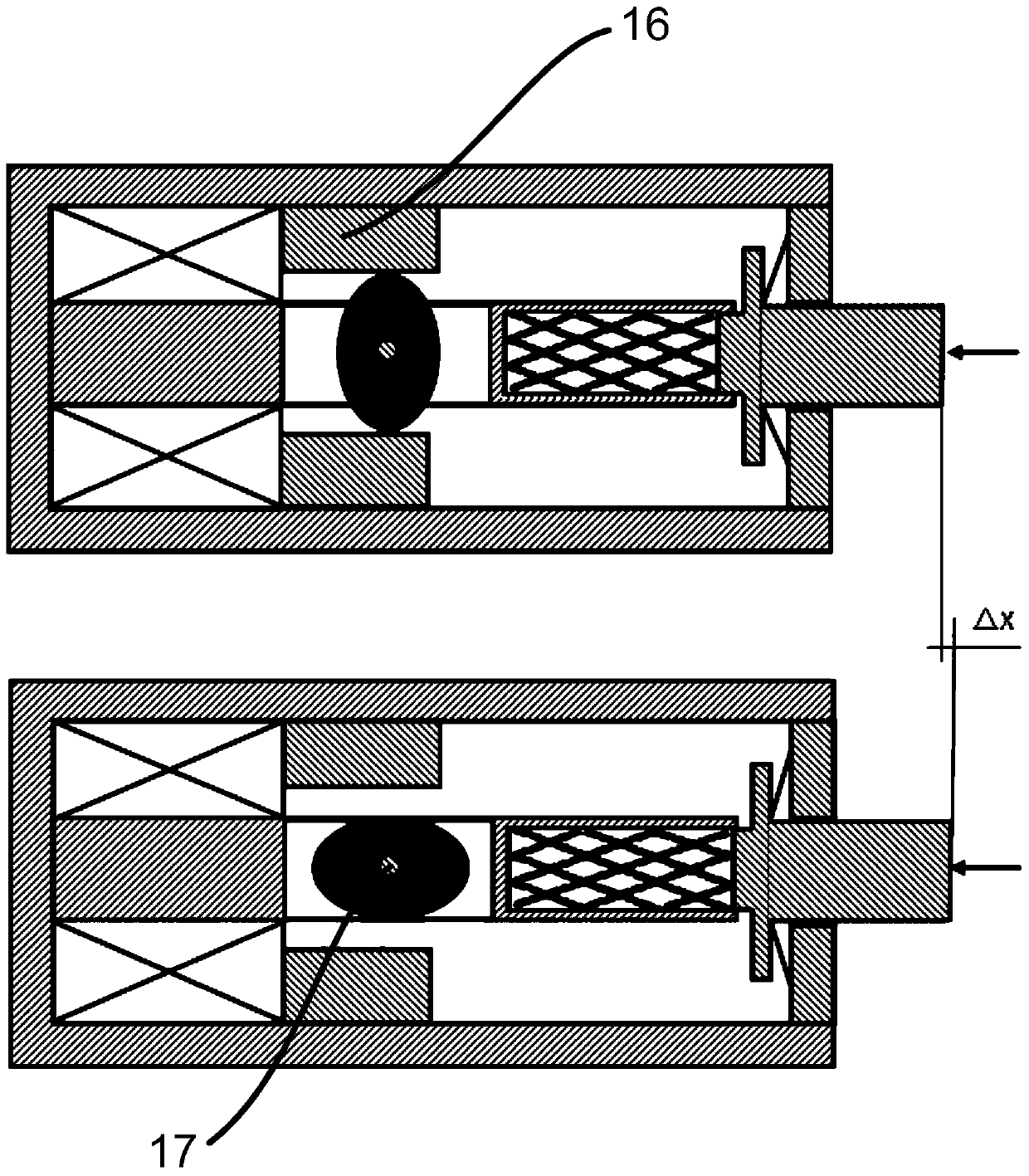
[0084] Embodiment 3 is a modification of Embodiment 1 or Embodiment 2. In this embodiment, the permanent magnet is an elliptical structure, and is arranged on the central axis rigid body through the rotating shaft.

[0085] In the initial state, the two magnetic poles of the permanent magnet are in the up and down direction. Under the force of the electromagnetic field of the electromagnetic coil, the permanent magnet deflects and rotates, and the magnetic poles change to the left and right directions. The magnetostrictive rod deforms under the force of the permanent magnet's magnetic field change.

[0086] Further, a magnetically permeable material body is provided outside the permanent magnet.

[0087] The magnetically permeable material body outside the magnet limits the magnetic field within the magnetically permeable material body, strengthens the magnetic field strength, and effectively controls the deformation of the displacement drive mechanism.


PUM


Abstract

The present invention provides an ultra-precision drive device based on electromagnetic-permanent magnet drive, including: an electromagnetic drive mechanism, a displacement drive mechanism and a displacement output mechanism, wherein the displacement drive mechanism is arranged in the control magnetic field of the electromagnetic drive mechanism, so The displacement drive mechanism produces deformation under the control magnetic field of the electromagnetic drive mechanism, and the displacement output mechanism is connected to the deformation output end of the displacement drive mechanism; the electromagnetic drive mechanism includes: a permanent magnet driver and a permanent magnet; the permanent magnet Under the action of the permanent magnet driving body, a changing magnetic field force is formed between the displacement driving mechanism, and the outer end of the displacement driving mechanism is the deformation output end; the present invention effectively isolates the permanent magnet driving body from the generation of electricity when the permanent magnet is energized. The heat can avoid the influence of heat on the driving device of the displacement driving mechanism, and realize the real precision driving.

Description

technical field [0001] The invention relates to the technical field of precision drives, in particular to an ultra-precision drive device based on electromagnetic-permanent magnet drive. Background technique [0002] In recent years, the field of electric and magnetostrictive materials has developed rapidly, and new smart materials such as giant magnetostrictive materials, piezoelectric ceramics and magnetostrictive shape memory alloys have been produced. These materials have high energy density and high output power. , precise telescopic deformation, etc., are usually used in the field of precision drive technology. [0003] The existing precision actuators using sensitive materials work on the principle that an electromagnetic drive device is installed outside the sensitive material, and the magnetic field is generated by energizing the electromagnetic drive device to deform the sensitive material, thereby affecting the output displacement of the output rod to form a preci...

Claims


Application Information

Patent Timeline
Patent Type & Authority Patents(China)
IPC IPC(8): H02N2/02H02N2/04
Inventor 杨斌堂
Owner SHANGHAI JIAO TONG UNIV
Learn More