Treatment liquid supply device and treatment liquid supply method
A technology for supplying devices and processing liquids, applied to liquid injection devices, devices for coating liquids on surfaces, thin material processing, etc., can solve problems such as changes, large-scale liquid processing devices, etc., and achieve the effect of suppressing the reduction in productivity
- Summary
- Abstract
- Description
- Claims
- Application Information
AI Technical Summary
Problems solved by technology
Method used
Image

Examples
no. 1 Embodiment approach
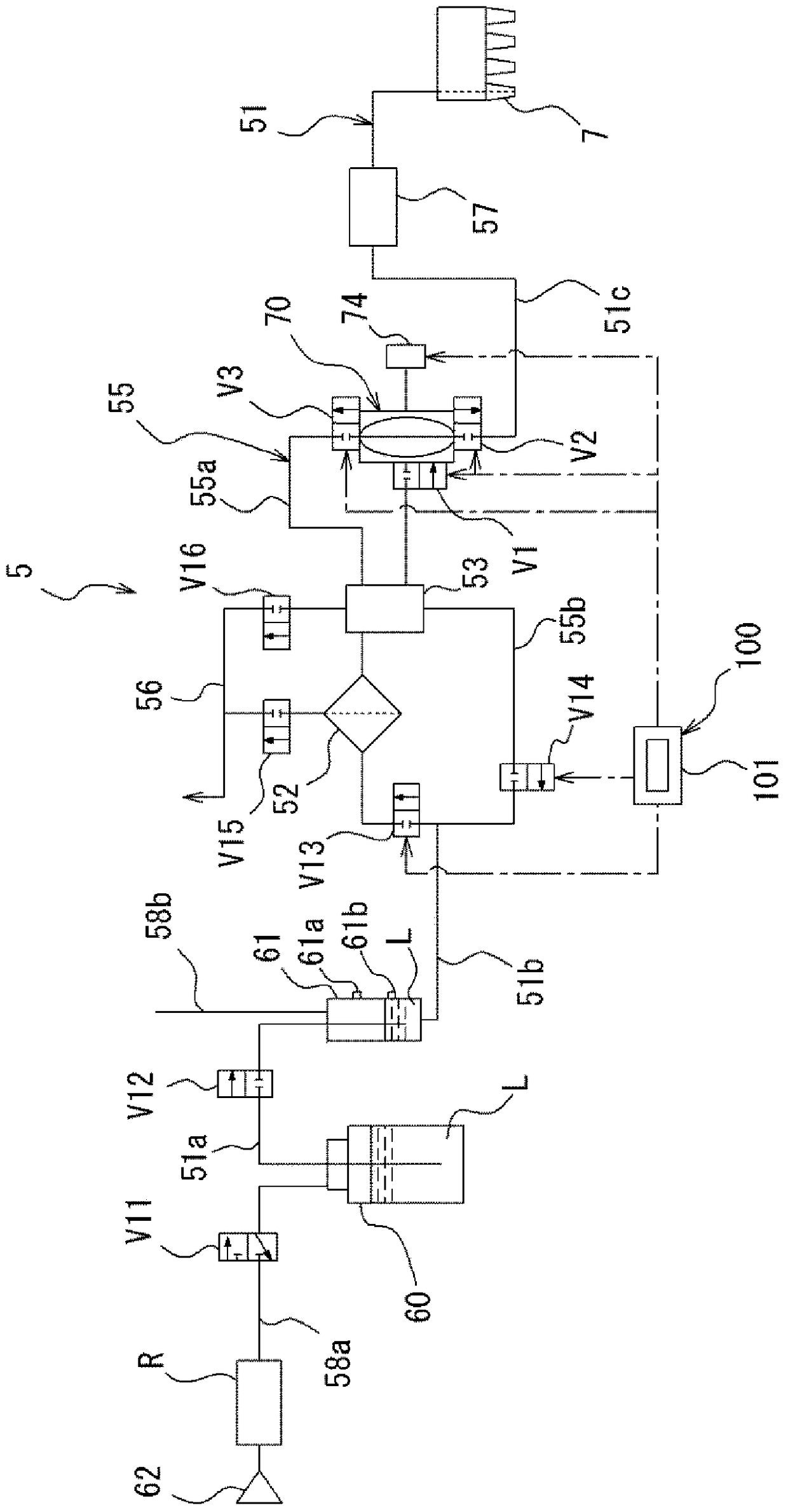
[0078] like image 3 As shown, the liquid processing device 5 of the present invention includes: a processing liquid container 60, which constitutes a processing liquid supply source for storing a resist liquid L as a processing liquid; a discharge nozzle 7, which serves as a discharge part for A resist liquid (processing liquid) L is discharged (supplied) to a wafer as a substrate to be processed; a supply line 51 connects the processing liquid container 60 and the discharge nozzle 7; a filter (filter device) 52 , which is sandwiched on the supply line 51 for filtering the resist liquid L; a pump 70, which is sandwiched on the part of the supply line 51 located on the secondary side of the filter 52; liquid collection part) 53, which is sandwiched on the part of the supply line 51 that connects the secondary side of the filter 52 and the primary side of the pump 70; the return line 55, which constitutes the discharge line of the pump 70 side and the primary side of the filte...
no. 2 Embodiment approach
[0113] Next, according to Figure 14 ~ Figure 17 A second embodiment of the liquid processing apparatus of the present invention will be described. In addition, in 2nd Embodiment, about the same structure as 1st Embodiment, the same code|symbol is attached|subjected to the same part, and description is abbreviate|omitted.
[0114] In the liquid processing device 5 of the second embodiment, the second return line 55b and the on-off valve V14 in the first embodiment are omitted, and the return line 65 connects the discharge side of the pump 70 and the collection side. The first return line 65 a connecting the tank 53 and the portion connecting the collection tank 53 and the secondary side of the filter 52 in the second treatment liquid supply line 51 b are formed.
[0115] Regarding steps S1 and S2, the operation of the second embodiment is similar to the operation performed in the first embodiment. Figure 12 Step S1( Figure 15 Shown to the pump chamber 72 suction resist li...
no. 3 Embodiment approach
[0126] according to Figure 18 ~ Figure 21 A third embodiment of the liquid processing apparatus of the present invention will be described. In addition, in 3rd Embodiment, about the same structure as 1st Embodiment and 2nd Embodiment, the same code|symbol is attached|subjected to the same part, and description is abbreviate|omitted.
[0127] The return line 85 of the third embodiment includes a first main return line 85a and a second main return line 85b constituting the main return line, and a circuit that connects the secondary side of the filter 52 and the primary side of the filter 52. Secondary return line 85c. The first main return line 85a connects the discharge side of the pump 70 to the catch tank 53, and the second main return line 85b connects the catch tank 53 to the part of the filter 52 in the second treatment liquid supply line 51b. part of the primary side is connected. In this case, the second main return line 85 b is connected to a portion of the second p...
PUM
 Abstract
Description
Claims
Application Information
 - R&D
- Intellectual Property
- Life Sciences
- Materials
- Tech Scout
- Unparalleled Data Quality
- Higher Quality Content
- 60% Fewer Hallucinations
Browse by: Latest US Patents, China's latest patents, Technical Efficacy Thesaurus, Application Domain, Technology Topic, Popular Technical Reports.
© 2025 PatSnap. All rights reserved.Legal|Privacy policy|Modern Slavery Act Transparency Statement|Sitemap|About US| Contact US: help@patsnap.com