
Casting device, solution film forming equipment and method

A casting film and casting technology, applied in the direction of flat products, coatings, household appliances, etc., can solve the problems of difficult to peel the cast film, and achieve the effect of suppressing interface confusion and blurring unevenness.

Active Publication Date: 2018-03-30
FUJIFILM CORP
View PDF6 Cites 0 Cited by
  • Summary
  • Abstract
  • Description
  • Claims
  • Application Information

AI Technical Summary

Problems solved by technology

DAC has strong adhesion to the support, so it is difficult to peel off the cast film from the support

Method used


Image

  • Casting device, solution film forming equipment and method
  • Casting device, solution film forming equipment and method
  • Casting device, solution film forming equipment and method

Examples


Embodiment

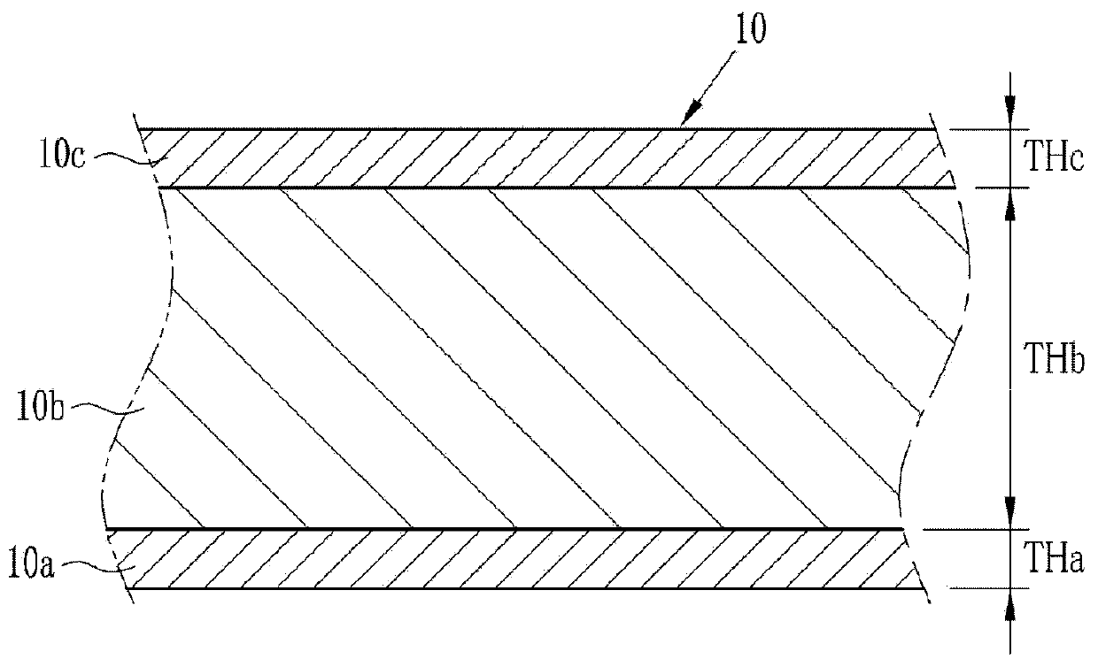
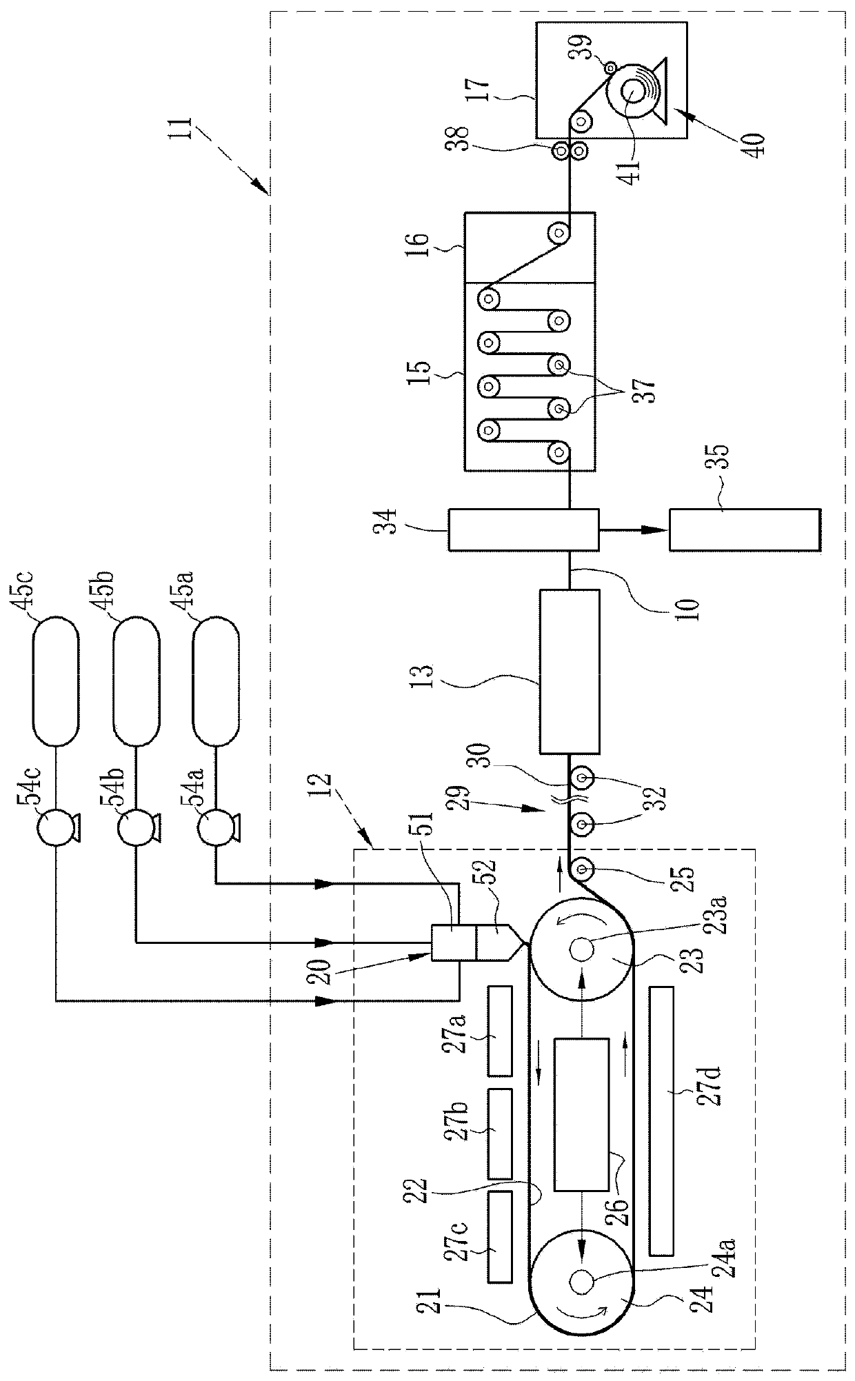
[0186] Example 1 to Example 4 were carried out as examples of the present invention. Each of the examples was implemented by using the solution film forming equipment 11, and the examples were performed by changing the shear viscosity ratios ηm / ηsa, ηm / ηsc and the above-mentioned radius of curvature R in the junction 62. Table 1 shows the ratio of each shear viscosity and the radius of curvature R. In addition, in any of the examples, the shear viscosity ηsa of the first dope 45a in the junction 62 is equal to the shear viscosity ηsc of the third dope 45c, so the ratio of the shear viscosity in Table 1 is simply expressed as "ηm / ηs".

[0187] The ratio of the shear viscosity is adjusted by adjusting the interval in the Y direction of the first dope slot portion 59a connected to the confluence portion 62, the third dope slot portion 59c, and the second dope slot portion 59b.

[0188] [Table 1]

[0189]

[0190] The width of the manufactured multilayer film 10 was 1500 mm....


PUM

PropertyMeasurementUnit
thicknessaaaaaaaaaa
viscosityaaaaaaaaaa
viscosityaaaaaaaaaa

Abstract

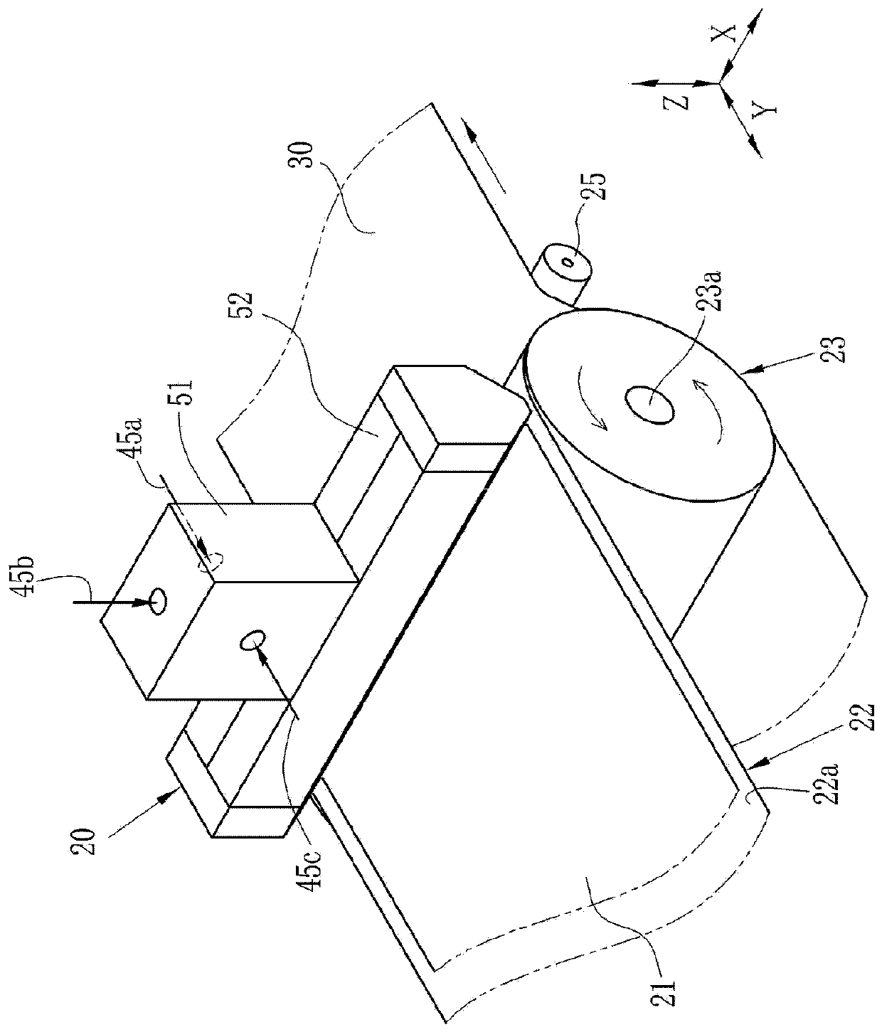
PROBLEM TO BE SOLVED: To provide a flow casting device preventing disarray of the interface between layers in a flow casting film in co-casting, and to provide a facility and method for forming a solution film.SOLUTION: A flow casting device is provided with a feed block and a flow casting die 52, and the feed block forms a laminar dope flow by making the first, second and third dopes confluent. In a confluent part, each of the ratios calculated by dividing the shear viscosity &eegr;m of the second dope by those of the first and third dopes &eegr;sa, &eegr;sc is set in a prescribed range. The flow casting die 52 has the first and second laminar flow slots 77, 78 and an outflow slot 79 as an inner flow path 69 toward an outflow port 69o. The boundary between the second laminar flow slot 78 and the outflow slot 79 in the inner wall face of the lip plates 71 is formed so that the distance to the outflow port 69o gradually decreases from a center in an X direction toward a side edge. The center is made to be in a curved shape having the curvature radius R of 100 mm or more.

Description

technical field [0001] The invention relates to a casting device, solution film-making equipment and a method. Background technique [0002] A light-transmitting polymer film (hereinafter referred to as a film) is used in various fields as an optical film. The optical film includes, for example, a photographic photosensitive film, a protective film for a polarizing plate that is a constituent member of a liquid crystal display device, a retardation film, and the like. [0003] A typical example of the light-transmitting polymer film is a cellulose acylate film having cellulose acylate as a polymer component. Ester films are used in optical films such as protective films of polarizing plates and retardation films, which are constituent members of liquid crystal display devices whose market has been expanding in recent years, represented by photographic photosensitive films. [0004] The main production methods of the film include the melt extrusion method and the solution f...

Claims


Application Information

Patent Timeline
Patent Type & Authority Patents(China)
IPC IPC(8): B29D7/01
CPCB29C41/26B29C41/42B29C41/46B29D7/01
Inventor 中村直贵
Owner FUJIFILM CORP
Learn More