
Sewing machine and sewing machine control method

A control method and technology for sewing machines, which are applied to sewing units, sewing machine components, sewing equipment, etc., and can solve problems such as jig falling off and poor sewing.

Inactive Publication Date: 2015-04-15
BROTHER KOGYO KK
View PDF7 Cites 9 Cited by
  • Summary
  • Abstract
  • Description
  • Claims
  • Application Information

AI Technical Summary

Problems solved by technology

When the sewing machine does not receive the jig enough, there is a problem that the jig falls off from the sewing machine, causing poor sewing

Method used


Image

  • Sewing machine and sewing machine control method
  • Sewing machine and sewing machine control method
  • Sewing machine and sewing machine control method

Examples


Embodiment Construction

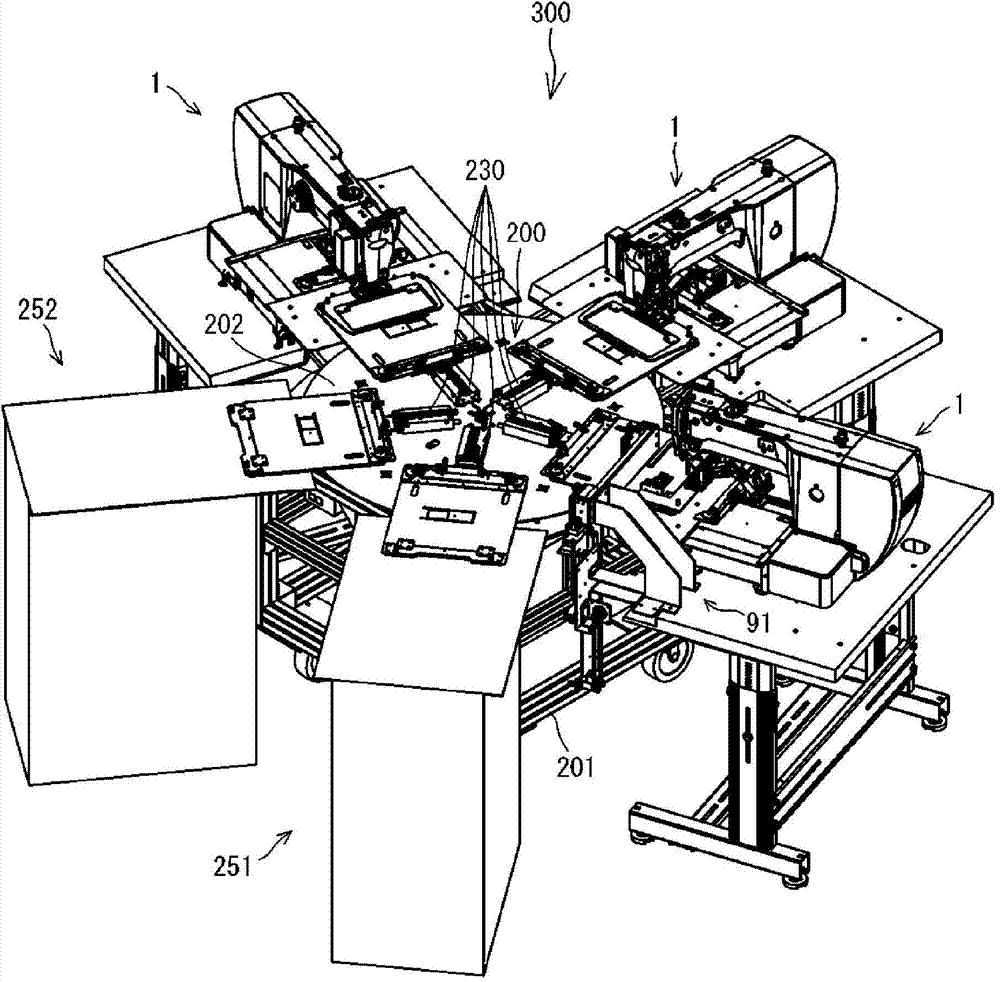
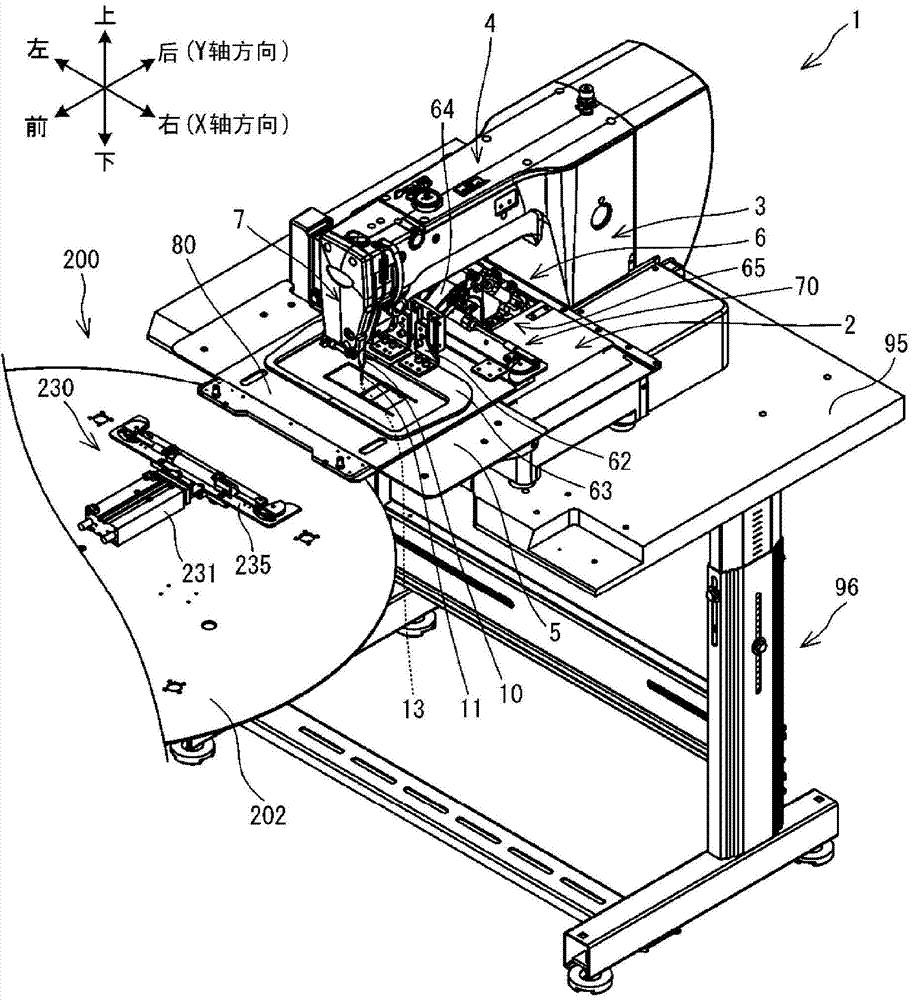
[0021] Embodiments of the present invention will be described. refer to figure 1 , figure 2 A schematic configuration of the sewing system 300 including the sewing machine 1 will be described. figure 2 The lower left, upper right, upper left, and lower right are the front, rear, left, and right of the sewing machine 1, respectively. The following description uses up and down, left and right, and front and rear as indicated by arrows in the figure.

[0022] Such as figure 1 As shown, the sewing system 300 includes a holding plate supply device 200 , three sewing machines 1 and two operating tables 251 , 252 . The three sewing machines 1 and the consoles 251 and 252 are arranged radially in plan view with the holding plate supply device 200 at the center. One of the three sewing machines 1 is provided with a component supply device 91 on the side. The through hole 826 of the accessory supply device 91 to the holding plate 80 (refer to Figure 4 ) to supply accessories f...


PUM


Abstract

The present invention relates to a sewing machine and a sewing machine control method. The sewing machine has two standby positions between the sewing machine and a holder plate supply mechanism. An operator uses an operation disc of the sewing machine to move a holder plate holding part. The holder plate holding part is positioned according to a holder plate holding part supply position of the holder plate supply mechanism. The sewing machine sets the position of the positioned holder plate holding plate as the first standby position, and sets a position closer to the sewing machine side than the first standby position as the second standby position. The holder plate holding part receives a holder plate at the first standby position and moves to the second standby position. After the holder plate holding part has moved to the second standby position, the sewing machine carries out sewing only when the holder plate is detected by a holder plate sensor.

Description

technical field [0001] The present invention relates to a sewing machine and a control method for the sewing machine. Background technique [0002] The sewing system includes a supply device and a sewing machine. The supply device supplies cloth to the sewing machine. The sewing machine receives the fabric from the supply device and sews according to the sewing program. Japanese Patent Publication No. 55081 of 1990 discloses a sewing system including a conveying device, a control device and a plurality of sewing machines. The conveying device is installed near the arrangement center of the plurality of sewing machines, and conveys the sewing object previously placed at a predetermined position to each sewing machine from the predetermined position, and conveys the sewing object between the sewing machines. The transport device has a working arm. The working arm can expand and contract along the radial direction of the rotation track of the base. The working arm detachab...

Claims


Application Information

Patent Timeline
Patent Type & Authority Applications(China)
IPC IPC(8): D05B25/00D05B39/00
CPCD05B25/00D05B33/00
Inventor 杉原良英
Owner BROTHER KOGYO KK
Learn More