Magnetic liquid magnetization viscosity testing method and device

A magnetic liquid and testing device technology, applied in the direction of measuring devices, flow characteristics, instruments, etc., can solve problems such as unusable, gap surface displacement, magnetic liquid support, etc., to achieve convenient adjustment, large radius of gyration, and small inertia Effect

Active Publication Date: 2017-09-29
NO 52 INST OF CHINA NORTH IND GRP CORP
View PDF6 Cites 2 Cited by
  • Summary
  • Abstract
  • Description
  • Claims
  • Application Information

AI Technical Summary

Problems solved by technology

On the one hand, it is not convenient to apply a strong magnetic field to the existing viscosity testing equipment. Even if an external magnetic field is applied, some viscometers that rely on gravity cannot be used, because the magnetic force will be greater than the effect of gravity
On the other hand, the common method requires a large amount of liquid samples each time
[0004] Chinese Patent Application Publication Nos. CN1737531A and CN2802498Y provide a method for testing the apparent viscosity of magnetic liquids using magnetic fluids with a similar magnetic accumulation structure, and controlling the strength of the external confinement magnetic field by increasing or decreasing the number of permanent magnet blocks in the magnetic accumulation structure. , on the one hand, it is inconvenient to replace the permanent magnet block each time, on the other hand, the change of the confined magnetic field is discontinuous, and the critical working magnetic field cannot be accurately measured. At the same time, the patent does not provide a method for measuring the strength of the working magnetic field.
The measurement method given in the Chinese patent CN2099316U is an improvement of the traditional kinematic viscosity test method. Although the permanent magnet is replaced by electromagnetism and the continuous change of the external magnetic field is realized, it is difficult to achieve and maintain a high viscosity in a long period of time. The strength of the magnetic field, and each test requires a large amount of liquid samples and consumes more electric energy, especially the electromagnetic coil will generate a lot of heat when it is working, it is difficult to control the temperature of the sample to be tested, especially it is difficult to achieve low temperature magnetization viscosity Determination of properties
However, with this design, there is only one magnetizing circuit, which can only apply a strong magnetic field to the magnetic liquid sample, and cannot reduce the magnetic flux on the magnetic circuit or the magnetic field strength applied to the constant gap to a relatively weak level; the rotation of the constant gap The radius is too small, but the inertia of the rotor is too large, which does not make full use of the structural space; and when the adjustable gap is adjusted, although the constant gap remains unchanged, the gap surface is relatively staggered, which will cause the magnetic liquid to be supported on the gap surface. moving phenomenon

Method used


Image

  • Magnetic liquid magnetization viscosity testing method and device
  • Magnetic liquid magnetization viscosity testing method and device
  • Magnetic liquid magnetization viscosity testing method and device

Examples


Embodiment 1

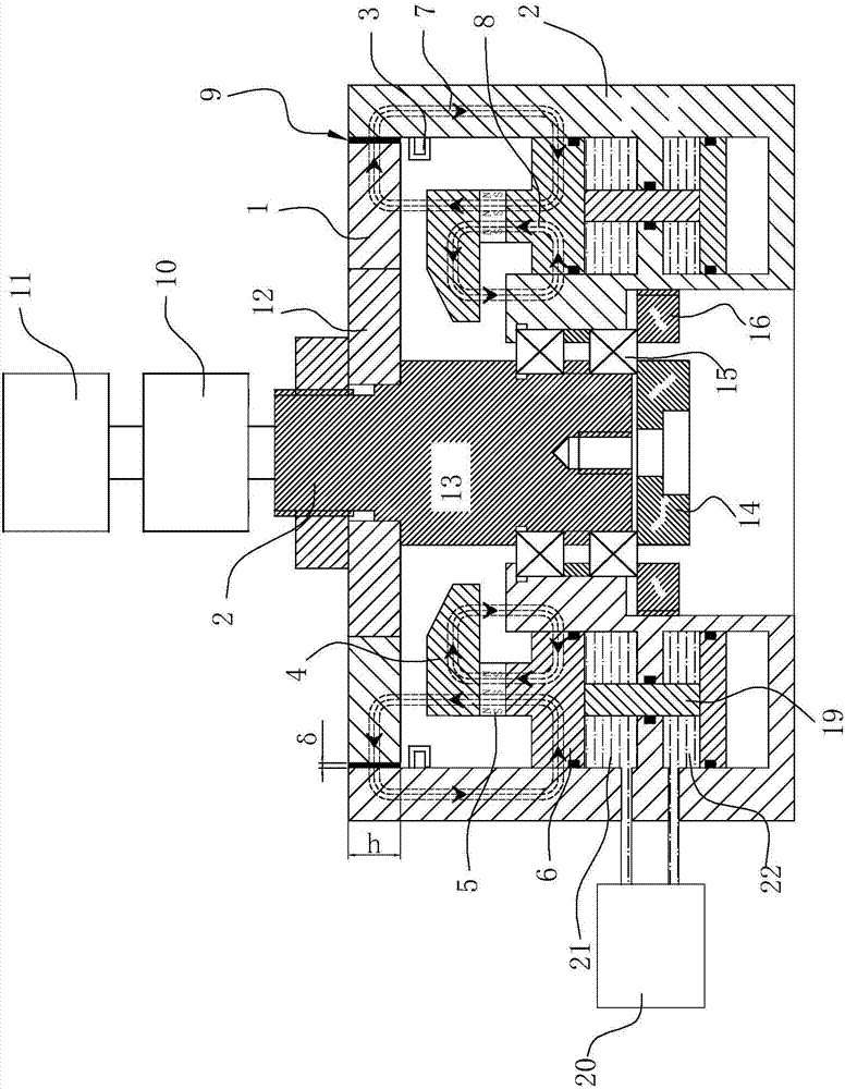
[0046] The magnetic liquid magnetization viscosity testing device of the present embodiment comprises a magnetically permeable rotor 1, an external magnetically permeable stator 2, an electromagnetic induction coil 3, an upper pole shoe ring 4, a permanent magnet ring 5, a lower pole shoe ring 6, a magnetic liquid 9, and a torque It is composed of a rotating speed testing device 10, a speed regulating motor 11, a non-magnetic centering rotor 12, a rotating shaft 13, a bearing 15 and its solid parts, wherein the torque and rotating speed testing device 10 is connected to the upper end of the rotating shaft 13, and the torque at the upper end of the rotating shaft 13 is There is a step below the rotational speed testing device 10, and the non-magnetic centering rotor 12 is sleeved on the step surface and is connected and fixed with the rotating shaft 13 by fasteners, and the magnetically conductive rotor 1 is fixed on the outside of the nonmagnetic centering rotor 12; the inner gu...

Embodiment 2

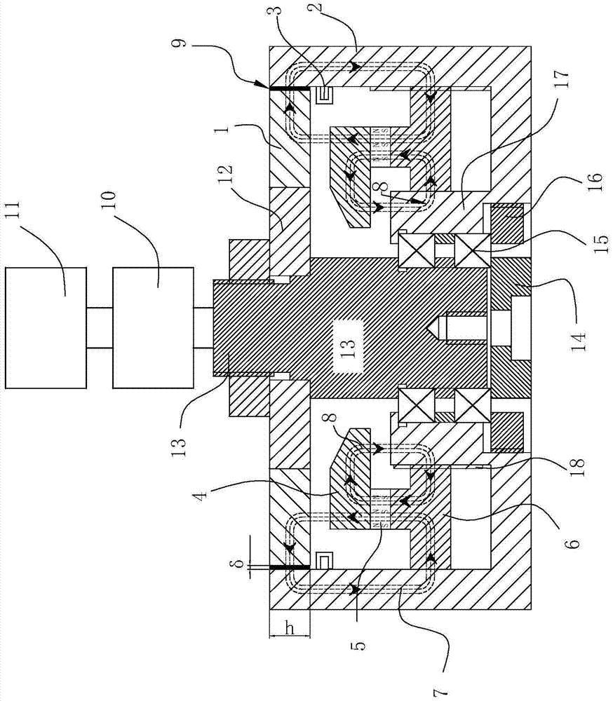
[0050] Such as image 3 As shown, the difference from Embodiment 1 is that an external driving thread 180 is set between the outer magnetically conductive stator 2 and the lower pole shoe ring 6, and the outer driving thread 180 is realized by rotating the outer magnetically conductive fixed ring and the lower pole shoe ring. The upper pole shoe ring 4, the permanent magnet ring 5 and the lower pole shoe ring 6 move up and down, so as to realize the continuous change of the magnetic field intensity in the axial constant gap δ.

Embodiment 3

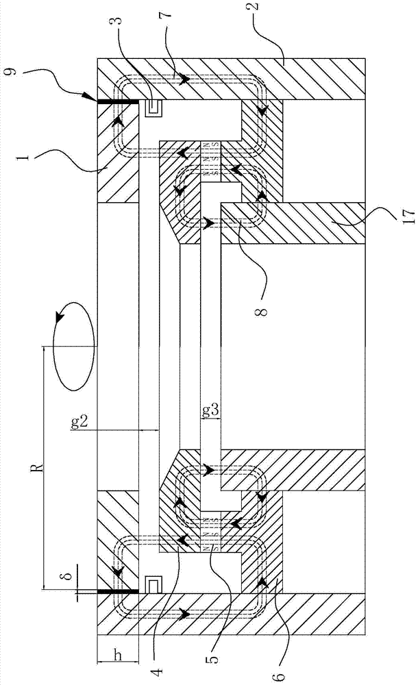
[0052] Such as Figure 4 As shown, the difference from Embodiment 1 and Embodiment 2 is that the lower pole shoe ring 6 is connected to the hydraulic drive connecting rod 19, and the hydraulic drive connecting rod 19 passes through the hydraulic unit 20, the upper hydraulic chamber 21, and the lower hydraulic chamber 22. The hydraulic pressure formed inside forms the upper and lower driving forces. When the hydraulic oil is pumped from the upper hydraulic chamber 21 into the lower hydraulic chamber 22, the driving connecting rod 19 moves upward. When the hydraulic oil is pumped from the lower hydraulic chamber 22 into the upper hydraulic chamber 21 , the driving connecting rod 19 moves downward, and the driving connecting rod 19 drives the upper pole shoe ring 4, the permanent magnet ring 5, and the lower pole shoe ring 6 to move up and down, thereby realizing the continuous change of the magnetic field intensity in the axial constant gap δ.


PUM


Abstract

A method and device for testing the magnetized viscosity of a magnetic liquid, using a permanent magnetic ring as a magnetic source, the confinement magnetic field is continuously adjustable from weak to strong, and is formed by a permanent magnetic ring surrounded by an inner magnetically conductive stator, an outer magnetically conductive stator, and a magnetically conductive rotor The cavity moves up and down, so that two radially adjustable gaps are formed between the upper pole shoe ring, the magnetically permeable rotor and the inner magnetically permeable stator, forming a magnetizing circuit and a magnetic flux leakage circuit, and then adjusting the force applied to the magnetic liquid material. Magnetic field strength, after starting the speed regulating motor, the magnetic liquid material is sheared through the rotation of the magnetically conductive rotor, and the viscosity characteristic is converted into shear force and measured by the torque testing device in the form of torque M; the magnetic flux is measured by the magnetic flux measuring device, and finally press The formula calculates the magnetization viscosity and flux density. The weak magnetic field of the present invention can be adjusted to a level close to zero, and the rotor that shears the magnetic liquid has a small inertia, a large radius of gyration, and is easy to adjust, and is more suitable for the viscosity-temperature curve of the magnetic liquid under low temperature and weak magnetic field and Measurement of magnetic viscosity curve.

Description

technical field [0001] The invention relates to a method and a device for testing the viscosity of a magnetic liquid and a magneto-rheological fluid, in particular to a method and a device for testing the magnetization viscosity of a magnetic fluid or a magneto-rheological material under the action of magnetic field magnetization. Background technique [0002] Magnetic liquids and magnetorheological materials are magnetic solid-liquid two-phase functional materials produced by stably dispersing magnetic particles in a certain carrier liquid through surfactants. Their overall shape, microstructure and viscosity are affected by an external magnetic field. Constraints and controls have a very broad application prospect in sealing, damping and vibration reduction, electromagnetic filtering, high-quality audio, sensing, braking, etc. The study of the viscosity characteristics of magnetic fluids and magnetorheological fluids in a magnetic field and at different temperatures is par...

Claims


Application Information

Patent Timeline
Patent Type & Authority Patents(China)
IPC IPC(8): G01N11/00
Inventor 李国斌赵宝荣倪培君陈丽云徐佳杜秀征唐纬虹曹学军闫薇方晓祖王志锋亓鲁臧建国王海波高晶信文君
Owner NO 52 INST OF CHINA NORTH IND GRP CORP
Why Eureka
Try Eureka