Straight slot pole staggered structure for large-scale PMSM

A technology of staggered pole and magnetic pole, applied in the field of rotor core and motor with the rotor core, can solve problems such as difficulty in technical realization, and achieve the purpose of weakening the harmonic potential of teeth, improving the efficiency of the motor, and weakening the additional rotation. moment effect

Active Publication Date: 2015-04-15
BEIJING MINGCHENG TECH DEV
View PDF7 Cites 0 Cited by
  • Summary
  • Abstract
  • Description
  • Claims
  • Application Information

AI Technical Summary

Problems solved by technology

[0006] For large self-starting permanent magnet synchronous motors or permanent magnet synchronous motors, the stator coi

Method used


Image

  • Straight slot pole staggered structure for large-scale PMSM
  • Straight slot pole staggered structure for large-scale PMSM

Examples


Embodiment Construction

[0017] The present invention will be described in further detail below in conjunction with the accompanying drawings and specific embodiments, but not as a limitation of the present invention.

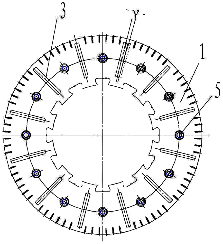
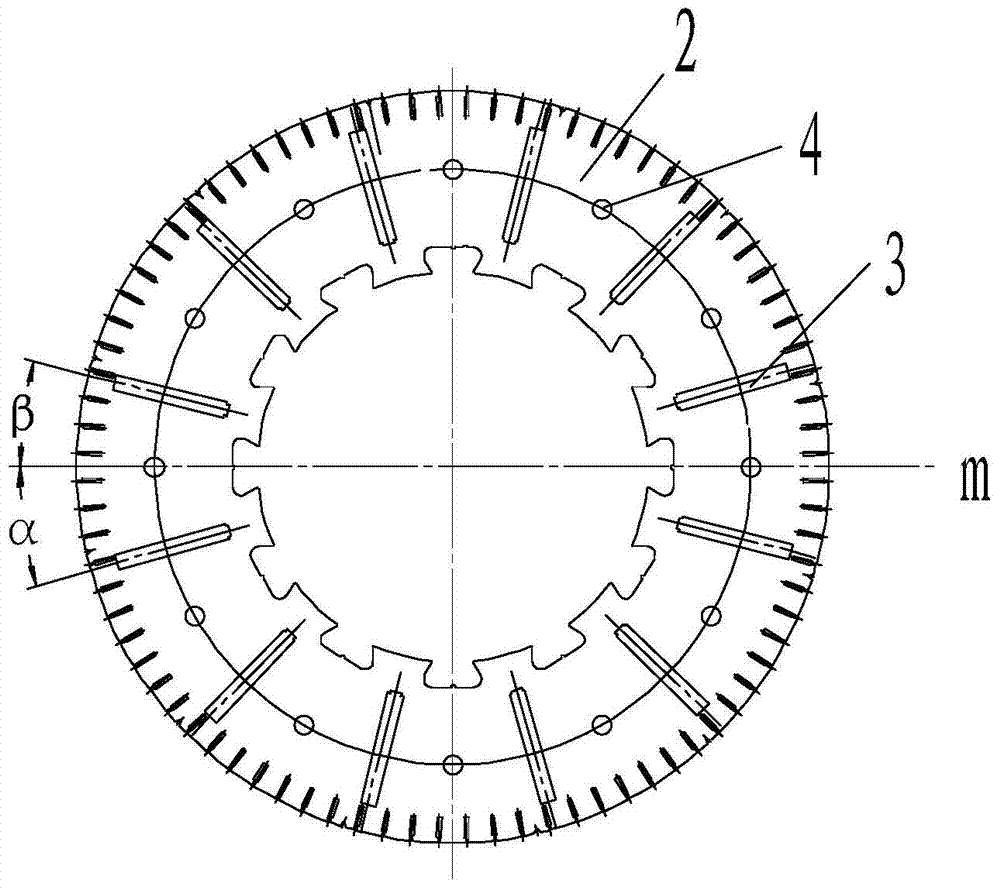
[0018] Such as figure 1 and figure 2 As shown, the rotor core 1 of the embodiment of the present invention is used to assemble with the straight slot stator core, and the stator core is provided with stator slots (not shown in the figure), and the rotor core 1 includes multiple slice rotor punch 2, such as figure 2 As shown, permanent magnet slots 3 for accommodating permanent magnets are evenly distributed on the rotor punch 2, and the permanent magnet slots 3 of a part of the rotor punch 2 are aligned and stacked together to form the first half of the rotor core (not shown in the figure ), the permanent magnet slots 3 of the other part of the rotor punch 2 are aligned and laminated together to form the second half-rotor core (not shown in the figure), the permanent magnet slots o...


PUM


Abstract

The invention discloses a large-scale PMSM rotor iron core formed by stacking a plurality of rotor punching sheets; the rotor iron core is uniformly provided with permanent magnets arranged in a staggered manner according to N-S polarity; the permanent magnets can be attached on a rotor iron core surface and can be nested in the rotor iron core; a whole rotor iron core is axially divided into two portions; magnetic pole arc center lines of certain rotor iron cores and magnetic pole arc center lines of other rotor iron cores are staggered with certain angle (staggered pole) in a periphery, and the angle equals to a half of an angle of two adjacent stator slots; a stator iron core matched with the pole staggered rotor iron core is a straight slot stator iron core formed by stacking a plurality of stator punching sheets; the straight slot is combined with the staggered pole so as to weaken tooth harmonic potential, and weaken additional torque caused by a tooth harmonic magnetic field, thus reducing motor electromagnetic vibration noises, and improving motor efficiency.

Description

technical field [0001] The invention relates to a rotor core and a motor with the rotor core, belonging to the technical field of motors. Background technique [0002] With the development of modern industry, the requirements for the operation accuracy and stability of various mechanical equipment are getting higher and higher. In addition, it is also required to reduce the environmental noise of work and life. The motor is the main power source of mechanical equipment. The vibration and noise of the motor are more and more concerned. Solving the vibration and noise of the motor is a must for motor designers and motor manufacturers. There are many reasons for the electromagnetic vibration noise of the motor, and there are many ways to weaken the harmonics and reduce the vibration noise, such as using short-distance windings for the stator, using magnetic slot wedges, etc. [0003] There are harmonics of various frequencies inside the motor. When the stator core adopts distr...

Claims


Application Information

Patent Timeline
IPC IPC(8): H02K1/27H02K21/02
CPCH02K1/27H02K21/02
Inventor 孙德全王艳杰袁静国王鹏徐长山
Owner BEIJING MINGCHENG TECH DEV
Why Eureka
Try Eureka