Built-in permanent magnet vibration reduction and noise reduction synchronous motor

A synchronous motor, built-in technology, applied in the direction of magnetic circuit static parts, magnetic circuit rotating parts, magnetic circuit shape/style/structure, etc. Durability, reduction of concealment and safety, etc., to improve the air gap magnetic field waveform, improve radial electromagnetic force, and reduce vibration and noise

Inactive Publication Date: 2017-01-11
HARBIN UNIV OF SCI & TECH
View PDF6 Cites 2 Cited by
  • Summary
  • Abstract
  • Description
  • Claims
  • Application Information

AI Technical Summary

Problems solved by technology

For military equipment, these vibrations and noises will greatly reduce its concealment and safety. For civilian equipment, it will affect the comfort and durability of the equipment, and it will also affect the work efficiency and safety of the nearby staff. Healthy body

Method used


Image

  • Built-in permanent magnet vibration reduction and noise reduction synchronous motor
  • Built-in permanent magnet vibration reduction and noise reduction synchronous motor
  • Built-in permanent magnet vibration reduction and noise reduction synchronous motor

Examples


specific Embodiment approach 1

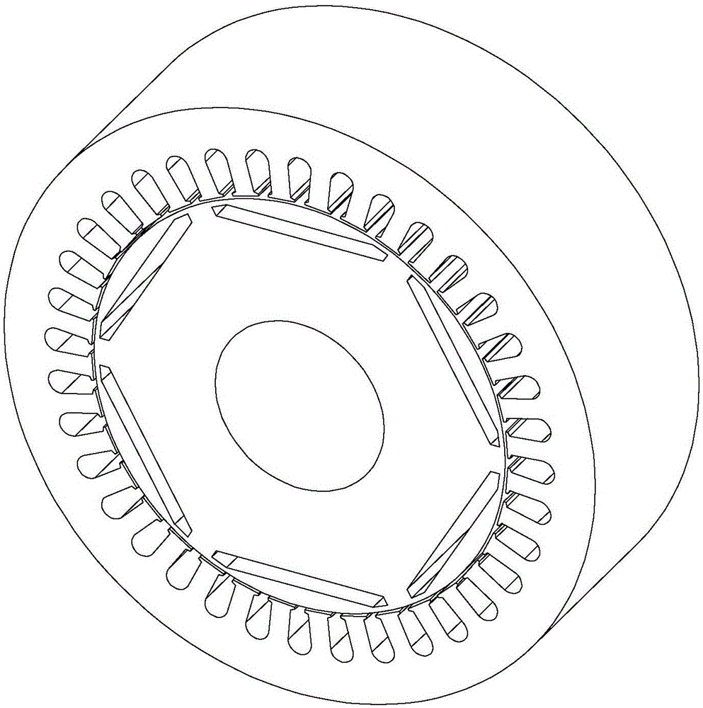
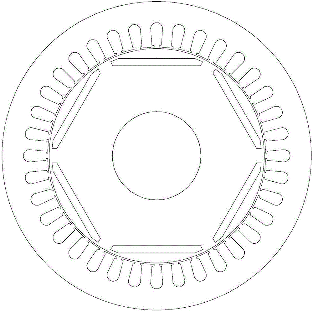
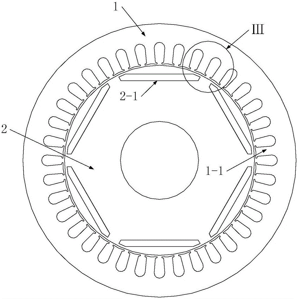
[0028] Specific implementation mode one: see image 3 and Figure 4 Describe this embodiment, the built-in permanent magnet vibration reduction and noise reduction synchronous motor described in this embodiment includes a stator 1 and a rotor 2, the stator 1 is set on the outside of the rotor 2, the two are coaxial, and between the two There is an air gap, and the addendum arc corresponding to each tooth portion 1-1 on the stator 1 is divided into two parts by the radial centerline of the tooth portion 1-1, and the two parts addendum arc The corresponding positions are respectively defined as: the front half teeth 1-1-1 and the second half teeth 1-1-2, the front half teeth 1-1-1 and the rear half teeth 1-1-2 are arranged counterclockwise in turn, the front half teeth The arc of the addendum of the tooth 1-1-1 is different from the arc of the addendum of the rear half tooth 1-1-2.

[0029] In this embodiment, the built-in permanent magnet vibration reduction and noise reducti...

specific Embodiment approach 2

[0031] Specific implementation mode two: see image 3 and Figure 4 Describe this embodiment. The difference between this embodiment and the built-in permanent magnet noise-reduction synchronous motor described in Embodiment 1 is that when the rotation direction of the rotor 2 is counterclockwise, the tooth tip of the first half tooth 1-1-1 The radian of the arc is greater than the arc of the addendum arc of the rear half tooth 1-1-2.

[0032] In this embodiment, when the rotation direction of the rotor 2 (that is, the positive direction of the magnetic field rotation) is counterclockwise, along this direction, in each tooth portion 1-1 on the stator, there are always the first half teeth 1-1- 1 is in contact with the magnetic field first, so when the magnetic field turns over a tooth 1-1 of the stator, the front half tooth 1-1-1 of the stator is subjected to the air gap magnetic field for a longer time than the second half tooth 1-1-2, so the front half tooth 1-1-1 is The a...

specific Embodiment approach 3

[0033] Embodiment 3: The difference between this embodiment and the built-in permanent magnet noise reduction synchronous motor described in Embodiment 1 is that when the rotation direction of the rotor 2 is in the clockwise direction, the addendum of the first half tooth 1-1-1 The radian of the arc is smaller than the arc of the addendum arc of the rear half tooth 1-1-2.

[0034] In this embodiment, when the rotation direction of the rotor 2 (that is, the positive direction of the magnetic field rotation) is clockwise, along this direction, in each tooth portion 1-1 on the stator, there are always the rear half teeth 1-1 -2 is in contact with the magnetic field first, so when the magnetic field turns over a tooth portion 1-1 of the stator, the second half tooth 1-1-2 of the stator is subjected to the air gap magnetic field for a longer time than the front half tooth 1-1-1, so the rear half tooth 1-1-2 will The radian of the addendum arc of the half tooth 1-1-2 is designed to ...


PUM


Abstract

The invention discloses a built-in permanent magnet vibration reduction and noise reduction synchronous motor and relates to the field of motor vibration reduction and noise reduction. Vibration and noise of an existing built-in permanent magnet motor are effectively suppressed. Two schemes are provided and are both improvements in teeth of a stator. Each tooth is divided into a front half tooth and a rear half tooth. According to the first scheme, the tooth top arc of each front half tooth is different from the tooth top arc of each rear half tooth in radian. According to the second scheme, the radial height of the interface between each front half tooth and the corresponding rear half tooth changes step by step. The width of an air gap corresponding to the center of each tooth is larger than the width of an air gap corresponding to any one end of each tooth. The synchronous motor is mainly applied to the motor driving field.

Description

technical field [0001] The invention relates to the fields of motor vibration reduction and noise reduction. Background technique [0002] The energy issue is one of the key issues that countries in the world are paying more attention to. my country has launched a series of policies and measures to vigorously advocate and promote the use of new energy. Some high-quality performances of permanent magnet motors have highlighted certain advantages in terms of size, performance, and cost, so they are increasingly favored by all walks of life. In recent years, as a new type of energy conversion device, permanent magnet motors have good controllability, wide speed range, simple structure, high power density, stability and reliability, and are not only widely used in military equipment such as aerospace, ships and ships. At the same time, it is also more and more frequently invested in civilian equipment such as automobiles, home appliances, medical care, and transportation. [...

Claims


Application Information

Patent Timeline
Patent Type & Authority Applications(China)
IPC IPC(8): H02K1/14H02K1/27
CPCH02K1/14H02K1/27
Inventor 谢颖李飞黎志伟蔡翔单雪婷
Owner HARBIN UNIV OF SCI & TECH
Why Eureka
Try Eureka