
Transmission processing method and optical transport network equipment for associated Fibre Channel signals

A fiber channel and processing method technology, applied in the field of communication, can solve the problems of high delay difference requirements, FC link data reception errors, and inability to adjust the transmission delay difference of FC ports, so as to meet the delay difference requirements and reduce the time delay. delay effect

Active Publication Date: 2018-01-12
CHINA TELECOM CORP LTD
View PDF5 Cites 0 Cited by
  • Summary
  • Abstract
  • Description
  • Claims
  • Application Information

AI Technical Summary

Problems solved by technology

[0005] FC links have high requirements on the delay difference between associated FC ports, and long-distance transmission is difficult to meet the 100ns-level delay difference requirements between different associated FC ports
For example, a 1Gbps FC link is jointly carried by 4 FC ports, and there is a requirement for data synchronization between FC ports. If the time delay difference between FC ports is too large, data reception errors will occur.
However, since other signal transmission basically does not require delay difference, the existing technology does not have an adjustment mechanism for signal transmission delay, and cannot adjust for the transmission delay difference between FC ports, resulting in the reception of data transmitted on the FC link. mistake

Method used


Image

  • Transmission processing method and optical transport network equipment for associated Fibre Channel signals
  • Transmission processing method and optical transport network equipment for associated Fibre Channel signals
  • Transmission processing method and optical transport network equipment for associated Fibre Channel signals

Examples


Embodiment Construction

[0035] Various exemplary embodiments of the present invention will now be described in detail with reference to the accompanying drawings. It should be noted that the relative arrangements of components and steps, numerical expressions and numerical values ​​set forth in these embodiments do not limit the scope of the present invention unless specifically stated otherwise.

[0036] At the same time, it should be understood that, for the convenience of description, the sizes of the various parts shown in the drawings are not drawn according to the actual proportional relationship.

[0037] The following description of at least one exemplary embodiment is merely illustrative in nature and in no way taken as limiting the invention, its application or uses.

[0038] Techniques, methods and devices known to those of ordinary skill in the relevant art may not be discussed in detail, but where appropriate, such techniques, methods and devices should be considered part of the descript...


PUM


Abstract

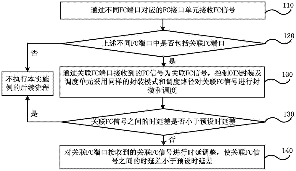
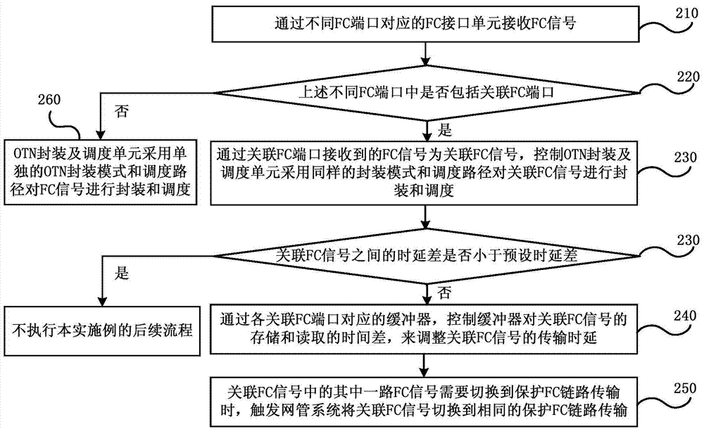
The embodiment of the present invention discloses a transmission processing method of associated fiber channel signals and optical transport network equipment, wherein the method includes: receiving FC signals through FC interface units corresponding to different FC ports; Whether the associated FC port is included in the different FC ports; if included, the FC signal received by the associated FC port is an associated FC signal, and the control OTN encapsulation and scheduling unit adopts the same encapsulation mode and scheduling path to encapsulate and process the associated FC signal Scheduling, and monitoring whether the delay difference between the associated FC signals is less than the preset delay difference; in response to the delay difference between the associated FC signals being not less than the preset delay difference, the associated FC signal received by the associated FC port Perform delay adjustment so that the delay difference between associated FC signals is smaller than the preset delay difference. The embodiment of the present invention enables an OTN device to control the transmission delay difference between associated FC ports, so as to meet the end-to-end delay difference requirement of associated FC signals.

Description

technical field [0001] The present invention relates to communication technology, in particular to a transmission processing method and optical transport network (Optical Transport Network, OTN) equipment associated with fiber channel signals. Background technique [0002] As a high-speed network technology, Fiber Channel (FC) technology is widely used in storage area networks. In recent years, FC technology has also been gradually used for remote data disaster recovery. As a mainstream transmission technology, OTN technology can meet the needs of multi-service, large-scale, large-capacity, and highly reliable transmission, scheduling, management, and protection. It is widely used in the metropolitan area network to carry private line services for large customers. [0003] At present, there is a need to use OTN to carry FC services in the metropolitan area network. An FC link may be carried by multiple FC ports. These FC ports are called associated FC ports. The FC signals ...

Claims


Application Information

Patent Timeline
Patent Type & Authority Patents(China)
IPC IPC(8): H04L12/70H04J3/16
Inventor 程明朱俊杨炜杰
Owner CHINA TELECOM CORP LTD
Learn More