
Partial mixed lamination board dislocation prevention method

A mixed-pressure, local technology, applied in the direction of stacking printed circuit boards, printed circuits, electrical components, etc., can solve the problems of poor PCB production quality, easy dislocation of daughter boards and motherboards, etc., and achieves low scrap rate and production quality. high effect

Active Publication Date: 2015-04-15
NEW FOUNDER HLDG DEV LLC +1
View PDF3 Cites 6 Cited by
  • Summary
  • Abstract
  • Description
  • Claims
  • Application Information

AI Technical Summary

Problems solved by technology

[0005] For this reason, the technical problem to be solved by the present invention is that in the prior art, during the pressing process of the PCB board, the sub-board and the mother board are prone to misalignment, resulting in poor production quality of the PCB board, and then providing a high-quality production prevention Dislocation design of partial mixed pressure plate

Method used


Image

  • Partial mixed lamination board dislocation prevention method
  • Partial mixed lamination board dislocation prevention method
  • Partial mixed lamination board dislocation prevention method

Examples


Embodiment 1

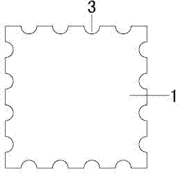
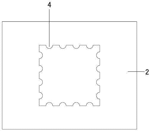
[0033] Such as Figure 1-2 As shown, a method for preventing partial mixed-press board misalignment described in Embodiment 1 includes a sub-board pretreatment step, a motherboard pre-treatment step, and a daughter-board motherboard mixing step;

[0034] After the sub-board pretreatment step, the following steps are carried out: forming several grooves 3 and / or bumps 4 on at least one edge of the sub-board 1;

[0035] After the mother board pretreatment step, the following steps are also carried out: on the corresponding edge of the mother board 2 suitable for the cavity in which the sub-board 1 is embedded, the protrusions 4 and the protrusions 4 and / or Groove 3;

[0036] The following steps are carried out before the mixed pressure step of the sub-board motherboard: the sub-board and the motherboard are inserted and matched with each other through the groove 3 and the protrusion 4 so that the sub-board 1 and the Embedded positioning is performed between the motherboards 2...

Embodiment 2

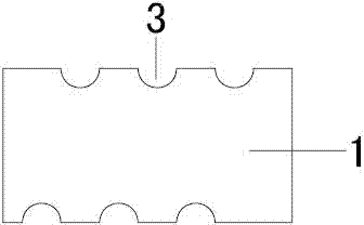
[0042] The difference between this embodiment and embodiment 1 is that in this embodiment 2, for the convenience of processing, only three grooves 3 are formed on two of the opposite edges of the sub-board 1, preferably two The grooves 3 on the edge are arranged in a staggered manner; three corresponding protrusions 4 are formed on two corresponding edges of the motherboard 2 .

Embodiment 3

[0044] The difference between this embodiment and Embodiments 1 and 2 is that, in this embodiment 3, grooves 3 and bumps 4 can be provided on the edge of the sub-board 1 at the same time, as Figure 5 As shown; the corresponding edge of the motherboard 2 can be provided with a mating projection 4 and a groove 3 at the same time, as Figure 6 As shown; in this embodiment, only the case where the groove 3 and the protruding block 4 are provided at the two opposite edges of the sub-board at the same time, of course, it can also be set in this way on the three or four edges of the sub-board.

[0045] The shape of the groove 3 and the bump 4 in the above three embodiments can be in various shapes, such as a rectangular block, a pointed block or an arc block, and in the above three embodiments, In order to facilitate processing and smooth insertion at the insertion joint, it is preferable to set the groove 3 and the protrusion 4 as circular arc blocks.


PUM


Abstract

The invention provides a partial mixed lamination board dislocation prevention method comprising daughter and mother board preprocessing steps and a daughter board and mother board mixed lamination step. The following step is performed after the daughter board preprocessing step: multiple grooves are formed on at least one edge of a daughter board; the following step is performed after the mother board preprocessing step: convex blocks, which are matched and inserted into the grooves, are formed on the corresponding edges of the cavity, which is suitable for embedding of the daughter board, of a mother board; the following step is performed before the daughter board and mother board mixed lamination step: the daughter board and mother board are positioned in an embedded way via mutual plugging and matching of the grooves and the convex blocks; and the daughter board is fixed and adhered on the mother board via lamination gel. According to the method, the daughter board and mother board are positioned in the embedded way via mutual matching of the grooves and the convex blocks so that the daughter board and mother board can be accurately positioned, relative displacement is not generated in the lamination process due to accurate positioning, and thus manufacturing quality of the mixed lamination board manufactured by using the method is high and rejection rate is low.

Description

technical field [0001] The invention relates to a mixed pressure plate, in particular to a design for preventing local mixed pressure plates from dislocation. Background technique [0002] In the process of manufacturing local high-frequency mixed-pressed PCB boards, usually only high-frequency materials need to be used locally. In production, local high-frequency material sub-boards are often mixed with ordinary material mother boards, but when the two are pressed together , because there is no positioning structure, it is easy to shift during operation, resulting in the problem of poor alignment between the sub-board and the motherboard, and in serious cases, it will cause the PCB board to be scrapped because of the misalignment of the board. [0003] In order to solve the above problems, the Chinese patent literature discloses a method for manufacturing a mixed-pressure printed circuit board, which includes: a high-frequency material daughter board, a mother board, and a ...

Claims


Application Information

Patent Timeline
Patent Type & Authority Applications(China)
IPC IPC(8): H05K3/36
CPCH05K3/368H05K2201/041H05K2201/049
Inventor 杨润伍张贤仕
Owner NEW FOUNDER HLDG DEV LLC
Learn More