Method for joining conveyer belt

A joining method and technology of conveyor belts, which are applied in the direction of belt fasteners, conveyors, belts/chains/gears, etc., can solve the problems of time required for steel cords, decreased joint strength, and greater adverse effects of conveyor belts, etc., to achieve polishing Process simplification, realization of quality, and shortening of joining work time

Active Publication Date: 2015-04-15
THE YOKOHAMA RUBBER CO LTD
View PDF7 Cites 5 Cited by
  • Summary
  • Abstract
  • Description
  • Claims
  • Application Information

AI Technical Summary

Problems solved by technology

At the site where the conveyor belt is used, there are restrictions on the working space and / or processing equipment, so there is a problem that cutting out the steel cord takes a lot of time.
[0010] In addition, the thicker the covering rubber, the more time is required to cut out the steel cord.
Therefore, the quality of the joint portion of the conveyor belt is adversely affected due to contamination of the joint portion by dust and / or water during the operation, resulting in a reduction in the joint strength.

Method used


Image

  • Method for joining conveyer belt
  • Method for joining conveyer belt
  • Method for joining conveyer belt

Examples


Embodiment Construction

[0030] Hereinafter, the method of joining a conveyor belt according to the present invention will be described based on the embodiments shown in the drawings.

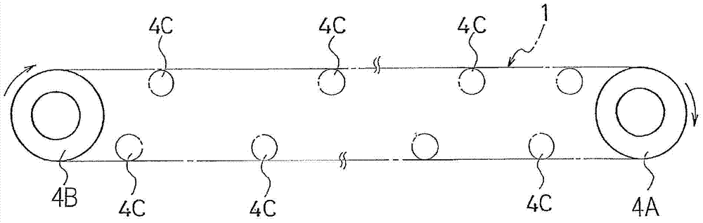
[0031] Such as figure 1 As illustrated, the conveyor belt (belt main body 1 ) is stretched between the driving roller 4A and the driven roller 4B provided at the front and rear portions of the belt conveyor. The belt main body 1 is wound around a driving roller 4A, a driven roller 4B, and a plurality of guide rollers 4C arranged between the driving roller 4A and the driven roller 4B.

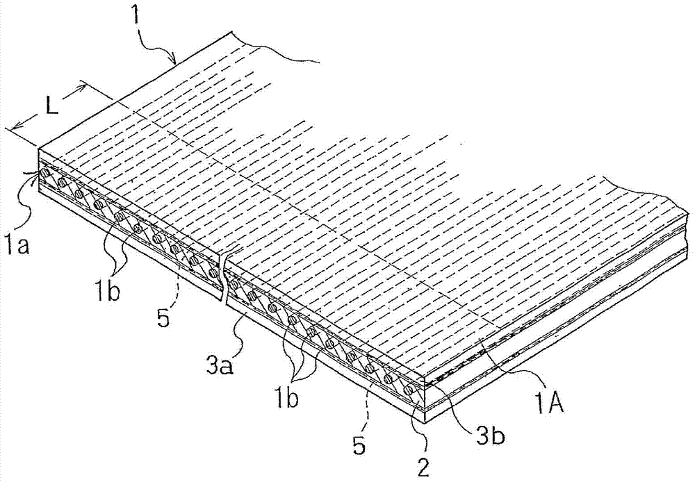
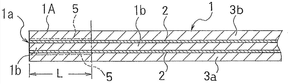
[0032] Such as figure 2 As illustrated, the conveyor belt (belt body 1 ) to which the present invention is directed is a conveyor belt having a core layer 1 a formed by arranging a plurality of steel cords 1 b side by side.

[0033] In the present invention, as image 3 As illustrated, the core layer 1 a of at least one end portion 1A in the longitudinal direction of the belt main body 1 is formed to be exposed in advance. The lengt...


PUM


Abstract

Provided is a method that is for joining a conveyor belt having as a core layer a steel cord and that can increase the quality of the join and reduce the joining work time for the ends in the lengthwise direction of the belt. The core layer (1a) is formed in a manner so as to be exposed ahead of time at the ends (1A) in the lengthwise direction of the belt main body (1), the top of the core layer (1a) is covered by a peeling member (5), and a cover rubber (3a, 3b) is laminated to the top of the peeling member (5), in which state the belt main body (1) is vulcanized/molded; the peeling member (5) is peeled, eliminating the cover rubber (3a, 3b) laminated onto the peeling member (5) and exposing the core layer (1a); the steel cord (1b) of the core layer (1a) to which to join to is inserted into the steel cord (1b) that is of the exposed core layer (1a) and of which alternate strands in the belt width direction have been severed to a predetermined length; and after laminating a cushion rubber (2) and a cover rubber (3a, 3b), the result is vulcanized, thus joining the core layers (1a) to each other.

Description

technical field [0001] The present invention relates to a method of joining a conveyor belt having a core layer formed by arranging a plurality of steel cords side by side. More specifically, the present invention relates to a method capable of shortening the joining operation time and improving the quality of the joint at the ends of the conveyor belt in the longitudinal direction. Improved conveyor belt splicing method. Background technique [0002] A conveyor belt having a core layer formed of steel cords is stretched between driving rollers and driven rollers provided at the front and rear of the belt conveyor. And, it is supported by a plurality of guide rollers arranged between the driving roller and the driven roller. After a certain period of use and / or in the case of damage during use, replace the entire conveyor belt and / or cut off the damaged portion and join a new conveyor belt to the longitudinal end of the belt body (for example, Refer to Patent Documents 1 a...

Claims


Application Information

Patent Timeline
Patent Type & Authority Applications(China)
IPC IPC(8): B65G15/30B65G15/36
CPCF16G3/10B65G15/30B65G15/36
Inventor 侯刚
Owner THE YOKOHAMA RUBBER CO LTD
Why Eureka
Try Eureka