Mounting method and mounting bases for locomotive underframe parts

An installation method and technology of the mounting seat, which are applied to railway car body parts, chassis, transportation and packaging, etc., can solve the problems of limited installation space, parts and pipelines, cable grinding, and bolt diameter increase, etc. Easy to disassemble, increase safety, reduce the effect of tightening torque

Inactive Publication Date: 2015-04-22
CRRC DALIAN CO LTD
View PDF6 Cites 12 Cited by
  • Summary
  • Abstract
  • Description
  • Claims
  • Application Information

AI Technical Summary

Problems solved by technology

The weight of the components installed in this way is carried by the bolts. With the operation of the locomotive, the bolts also bear the transverse shear force, which increases the risk factor of bolt fracture and brings hidden dangers to driving safety.
If the weight of the component is heavy, the diameter and quantity of the bolts to be used should be increased correspondingly, and the tightening torque is relatively large. When the components installed under the vehicle need to be installed and disassembled more frequently, it will be time-consuming and laborious.
However, there are a lot of components installed under the vehicle. In addition to these large box components, there are also pipelines, cables, etc. The installation space is very limited, and the installation position of the components cannot be adjusted, which will easily cause friction between the components and the pipelines and cables. , there is a security risk

Method used


Image

  • Mounting method and mounting bases for locomotive underframe parts
  • Mounting method and mounting bases for locomotive underframe parts

Examples


Embodiment Construction

[0019] In order to make the purpose, technical solutions and advantages of the present invention clearer, the technical solutions of the present invention are clearly and completely described below in conjunction with the drawings in the embodiments of the present invention. Obviously, the described embodiments are part of the embodiments of the present invention , but not all examples. Based on the embodiments of the present invention, all other embodiments obtained by persons of ordinary skill in the art without making creative efforts belong to the protection scope of the present invention.

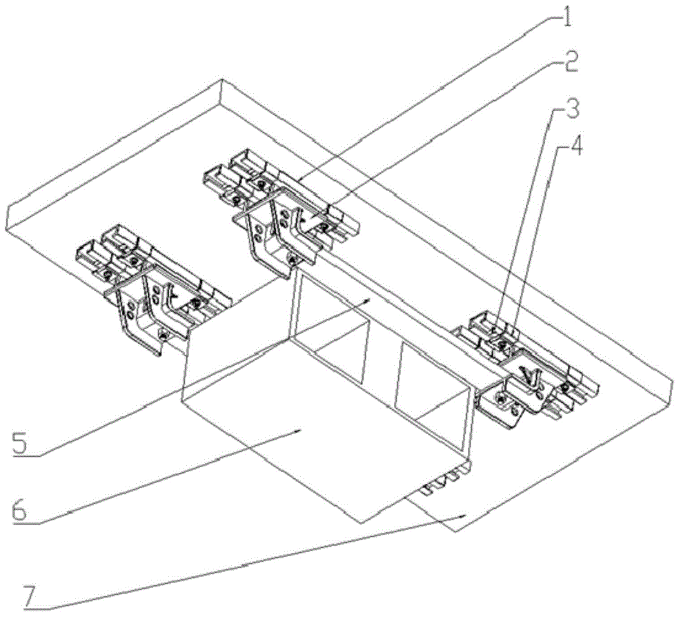
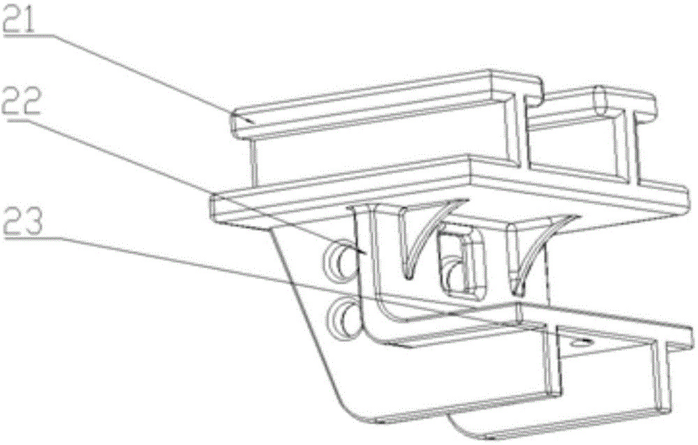
[0020] see figure 1 , a method for installing parts of a locomotive underframe according to the present invention, through the slideway 1 welded on the vehicle body underframe 7 in advance, the mounting seat 2 used in conjunction with the slideway 1 and the mounting beam 5 on the parts, and then through the limit stop The block 3 and the positioning block 4 are fixed, which can realiz...


PUM


Abstract

The invention discloses a mounting method and mounting bases for locomotive underframe parts, and belongs to the technical field of railway locomotives. In order to mount and dismount the parts on a locomotive body underframe conveniently and adjust the positions of the locomotive underframe mounting parts, sliding rails are welded to the locomotive body underframe in advance, mounting beams are welded on one part to be mounted, the mounting bases are arranged at the ends of the mounting beams, then guide rails on the mounting bases are matched with the sliding rails, and the mounting bases are fixed by limiting stopping blocks and positioning stopping blocks. The mounting method is suitable for smoothly mounting most of locomotive underframe parts, the weights of the mounted parts are borne by a locomotive body and the mounting bases, and bolts are prevented from bearing transverse shear force in the locomotive operation process. The sliding rail type mounting structure is used by the locomotive underframe parts, the positions of the locomotive underframe mounting parts can be adjusted easily, the mounted parts can be prevented from abrading pipelines and cables under a locomotive, and therefore the operation safety of the locomotive is improved.

Description

technical field [0001] The invention relates to the installation of locomotive underframe components and belongs to the technical field of railway locomotives. Background technique [0002] During the design process of railway locomotives, some components such as battery boxes, fuel tanks, transformers, etc. need to be installed on the chassis of the locomotive. There is a mounting seat. During installation, use hydraulic lifting equipment or a crane to lift the parts to be installed. After aligning the mounting seats, use bolts for fixed connection. The weight of the parts installed in this way is all carried by the bolts. As the locomotive runs, the bolts also carry the transverse shear force, which increases the risk factor of bolt fracture and brings hidden dangers to driving safety. If the weight of the parts is large, the diameter and quantity of the bolts that need to be used will be increased accordingly, and the tightening torque will be larger. When the parts inst...

Claims


Application Information

Patent Timeline
Patent Type & Authority Applications(China)
IPC IPC(8): B61F1/08
CPCB61F1/08
Inventor 李国栋孙秀玲杜鑫于跃
Owner CRRC DALIAN CO LTD
Why Eureka
Try Eureka