
Double continuously variable transmission steering mechanism

A technology of steering mechanism and belt-type stepless speed change, which is applied in the direction of steering mechanism, non-deflectable wheel steering, mechanical equipment, etc., and can solve the problems of safety accidents that are easy to roll over, difficult to apply to tracked vehicles, and difficult to turn to tracked vehicles. , to achieve high safety, ensure steering flexibility, and improve the safety factor

Active Publication Date: 2015-04-22
LANS INTELLIGENT ROBOT CHANGSHA CO LTD
View PDF7 Cites 4 Cited by
  • Summary
  • Abstract
  • Description
  • Claims
  • Application Information

AI Technical Summary

Problems solved by technology

Tracked vehicles are different from wheeled vehicles. The steering method of wheeled vehicles is difficult to apply to tracked vehicles. The steering methods of conventional tracked vehicles and high-speed tracked vehicles are also very different. Conventional tracked vehicles Steering is achieved by stopping one side of the track and driving the other side normally. However, if one side of a tracked vehicle running at high speed stops, it is very easy to overturn and cause a serious safety accident. It is difficult to apply Tracked vehicles traveling at high speed

Method used


Image

  • Double continuously variable transmission steering mechanism
  • Double continuously variable transmission steering mechanism
  • Double continuously variable transmission steering mechanism

Examples


Embodiment Construction

[0018] In order to facilitate the understanding of those skilled in the art, the present invention will be further described below in conjunction with the embodiments and accompanying drawings, and the contents mentioned in the embodiments are not intended to limit the present invention.

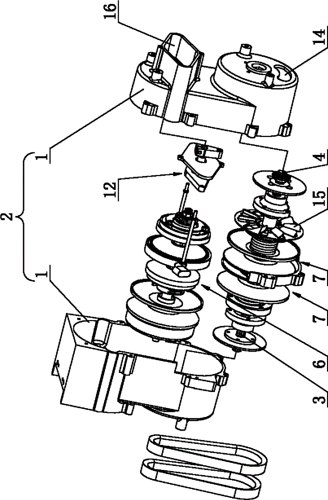
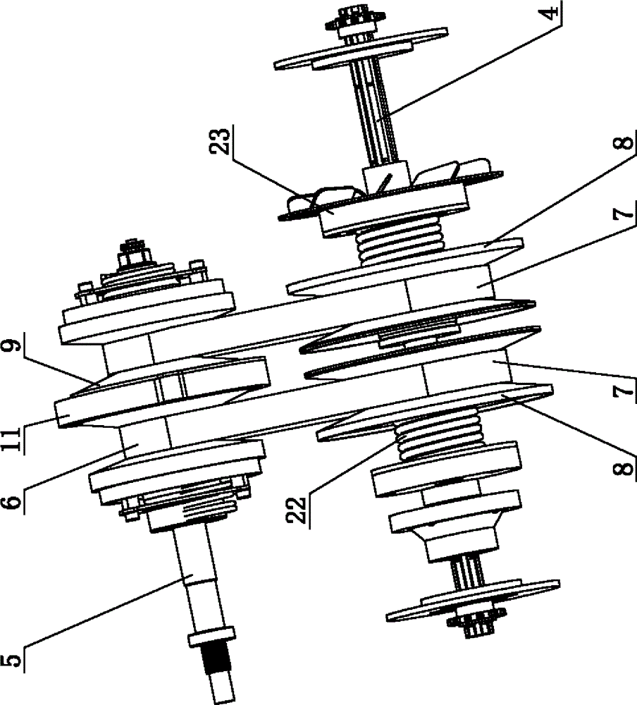
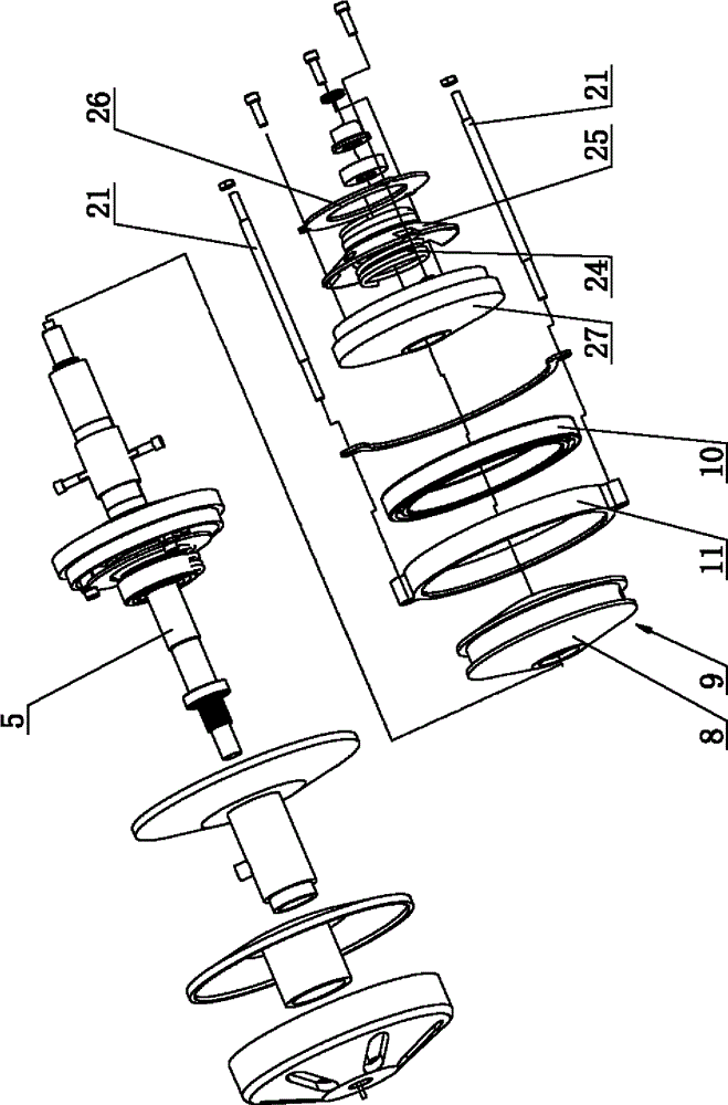
[0019] Such as Figure 1 to Figure 4 As shown, a double stepless speed change steering mechanism includes a reduction box body 2, a left output shaft 3 installed in the reduction box body 2, a right output shaft 4 and a main drive shaft 5, and the reduction box body 2 is composed of two shells The body 1 is combined to form, and the main transmission shaft 5 is respectively connected to the left output shaft 3 and the right output shaft 4 through two belt-type continuously variable transmission mechanisms. The belt-type continuously variable transmission mechanism includes two driving pulleys 6 installed on the main transmission shaft 5 and two driven pulleys 7 respectively installed on the ...


PUM

PropertyMeasurementUnit
Diameteraaaaaaaaaa
Diameteraaaaaaaaaa
Diameteraaaaaaaaaa

Abstract

The invention relates to the technical field of individual tracked vehicles, in particular to a double continuously variable transmission steering mechanism. The steering mechanism comprises a speed reduction box, a left output shaft, a right output shaft and a main transmission shaft, the left output shaft, the right output shaft and the main transmission shaft are arranged in the speed reduction box, the speed reduction box is formed by oppositely combining two shells, the main transmission shaft is in transmission connection with the left output shaft and the right output shaft through two belted continuously variable transmission mechanisms, and the rotation speed ratio of the left output shaft to the right output shaft is 1:4-4:1. In the steering process, the larger left and right displacement of a speed regulation wheel disc is, the larger the width difference of two driving belt wheels is, the larger the steering angle of the left output shaft and the steering angle of the right output shaft are, and therefore the large and small radius cornering control function is achieved. The steering mechanism is suitable for small tracked vehicles under various road condition environments; by means of specific rotation speed differences, steering flexibility of the vehicles can be guaranteed at a low speed, security can also be guaranteed when the vehicles turn a corner at a high speed, side turn caused by overhasty cornering is prevented, safety is high, and practicability is high.

Description

technical field [0001] The invention relates to the technical field of personal crawler vehicles, in particular to a dual continuously variable speed steering mechanism. Background technique [0002] The development of the steering system of tracked vehicles has roughly gone through steering clutches and hydromechanical differential steering systems. Personal Caterpillar tracked vehicles have been proposed. For example, U.S. Patent No. 5,305,846 to Martin discloses a personal tracked vehicle intended for use by an individual comprising a pair of Caterpillar tracks mounted on Below the platform the user is standing on. Operation of the vehicle—including steering the vehicle by varying the relative speeds of the drive tracks—is controlled by manually operating the controls. [0003] While it is possible to construct a tracked vehicle as disclosed by Martin, it suffers from several drawbacks. Tracked vehicles are different from wheeled vehicles. The steering method of wheel...

Claims


Application Information

Patent Timeline
IPC IPC(8): B62D11/10F16H9/04
CPCB62D11/10F16H9/18F16H2009/163
Inventor 陈全强
Owner LANS INTELLIGENT ROBOT CHANGSHA CO LTD
Learn More