Swing sheet structure for screw feeding device

A technology of feeding device and sheet structure, which is applied in the direction of conveyor objects, transportation and packaging, etc., can solve the problems affecting the normal transportation of materials, unfavorable transportation and use, and different screw states, so as to ensure normal transportation, simple structure and low cost. The effect of manufacturing costs and workpiece processing costs

Inactive Publication Date: 2015-04-22
苏州格林电子设备有限公司
View PDF6 Cites 0 Cited by
  • Summary
  • Abstract
  • Description
  • Claims
  • Application Information

AI Technical Summary

Problems solved by technology

In the process of actually using the feeding device for screw conveying, we found that the screws are prone to different states and tilted, which is not conducive to the transmission and use of subsequent processes; thus affecting the normal conveying of some materials

Method used


Image

  • Swing sheet structure for screw feeding device
  • Swing sheet structure for screw feeding device

Examples


Embodiment Construction

[0018] The implementation of the present invention will be illustrated by specific specific examples below, and those skilled in the art can easily understand other advantages and effects of the present invention from the contents disclosed in this specification.

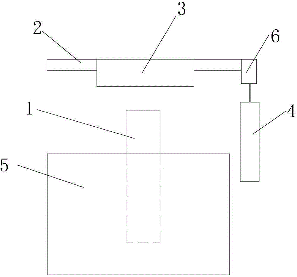
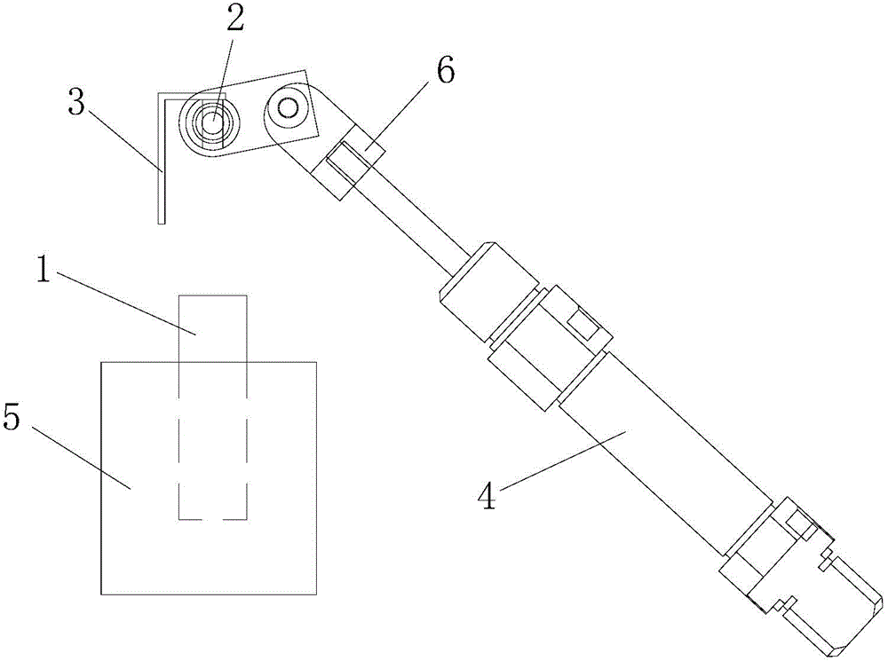
[0019] see Figure 1 to Figure 2 . It should be noted that the structures, proportions, sizes, etc. shown in the drawings attached to this specification are only used to match the content disclosed in the specification, for those who are familiar with this technology to understand and read, and are not used to limit the implementation of the present invention. Limiting conditions, so there is no technical substantive meaning, any modification of structure, change of proportional relationship or adjustment of size, without affecting the effect and purpose of the present invention, should still fall within the scope of the present invention. The disclosed technical content must be within the scope covered. At the sa...


PUM


Abstract

A swing sheet structure for a screw feeding device comprises a conveying channel. The swing sheet structure comprises a swing rod, a swing sheet and a swing air cylinder. The swing rod is erected over the conveying channel. The part, in the conveying channel direction, of the swing sheet is arranged on the swing rod, and the acting end of the swing air cylinder is in transmission connection with one end of the swing rod and drives the swing rod to drive the swing sheet to swing in a reciprocating mode. The swing sheet structure is arranged above the feeding channel, screws with the screw head facing directions not meeting the requirement can be effectively removed, a material collecting hopper is arranged below the feeding channel and can collect the removed screws in time, the phenomenon that the screws disengage and fall onto the ground, and material waste is caused is avoided, normal conveying of the screws is guaranteed, and the screw conveying efficiency is improved. The swing sheet structure is simple and high in stability, and the manufacturing cost and the workpiece machining cost are reduced.

Description

technical field [0001] The invention belongs to the technical field of material conveying devices, and relates to a screw feeding device, in particular to a swing plate structure for the screw feeding device. Background technique [0002] In the production field of many existing products, especially in the assembly process of electronic products, it is necessary to assemble specific mechanisms or components by locking multiple screws. With the higher and higher requirements for automation, especially in the field of assembly line production or in the process of screw screening, it is often necessary to arrange multiple screws in a certain order for access or conveying and screening, so as to increase Improve factory production efficiency, increase labor rate, and reduce labor costs. Therefore, various screw feeding devices have been developed. [0003] Commonly used screw feeding devices generally include a base, a vibrating device and a feeding tray. The vibrating device ...

Claims


Application Information

Patent Timeline
Patent Type & Authority Applications(China)
IPC IPC(8): B65G47/256
Inventor 邱文良
Owner 苏州格林电子设备有限公司
Why Eureka
Try Eureka