Friction wheel driving mechanism
A driving mechanism and friction wheel technology, applied in the direction of friction transmission device, electromechanical device, transmission element, etc., can solve the problems of wasting electric power resources, complicated operation, undiscovered, etc., and achieve the effect of saving resources
- Summary
- Abstract
- Description
- Claims
- Application Information
AI Technical Summary
Problems solved by technology
Method used
Image

Examples
Embodiment Construction
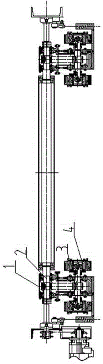
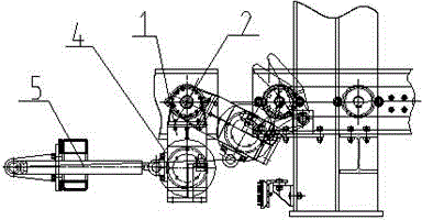
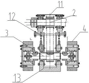
[0018] Such as Figures 1 to 3 The friction wheel driving mechanism shown is arranged at the front end of the base of the logistics trolley, and includes a friction wheel support seat 1 , a drive shaft 2 , an output shaft 3 , a friction wheel 4 , a rotating drive mechanism and a pressing mechanism 5 .
[0019] The drive shaft 2 is set at the front end of the logistics trolley, and a free roller is set on the drive shaft 2. The drive shaft 2 is driven by a rotating drive mechanism. One end of the drive shaft 2 is provided with a friction wheel supporting seat 1 that rotates around the drive shaft 2 through the bearing assembly A. The friction The lower end of the wheel support seat 1 is provided with an output shaft 3 crossing the friction wheel support seat 1, and a friction wheel 4 is respectively provided at both ends of the output shaft 3.
[0020] The pressing mechanism 5 is arranged on the base and the front end is connected with the lower end of the friction wheel sup...
PUM
 Abstract
Description
Claims
Application Information
 - R&D
- Intellectual Property
- Life Sciences
- Materials
- Tech Scout
- Unparalleled Data Quality
- Higher Quality Content
- 60% Fewer Hallucinations
Browse by: Latest US Patents, China's latest patents, Technical Efficacy Thesaurus, Application Domain, Technology Topic, Popular Technical Reports.
© 2025 PatSnap. All rights reserved.Legal|Privacy policy|Modern Slavery Act Transparency Statement|Sitemap|About US| Contact US: help@patsnap.com