Pneumatic globe valve

A technology of pneumatic shut-off valve and valve sleeve, applied in the direction of lift valve, valve details, valve device, etc., can solve the problems of object hitting accident, damage, flying pneumatic shell 1, etc., and achieve the effect of avoiding object hitting accident

Active Publication Date: 2017-06-06
四川安东油气工程技术服务有限公司
View PDF7 Cites 0 Cited by
  • Summary
  • Abstract
  • Description
  • Claims
  • Application Information

AI Technical Summary

Problems solved by technology

The ejector rod 2 and the pneumatic casing 1 will be seriously damaged when they are subjected to high pressure for a long time, and when the high pressure reaches a certain level, components such as the pneumatic casing 1, ejector rod 2 and valve core 5 will be blown away, causing objects to strike ACCIDENT

Method used


Image

  • Pneumatic globe valve
  • Pneumatic globe valve
  • Pneumatic globe valve

Examples


Embodiment Construction

[0020] The present invention will be further described in detail below in conjunction with the accompanying drawings and embodiments.

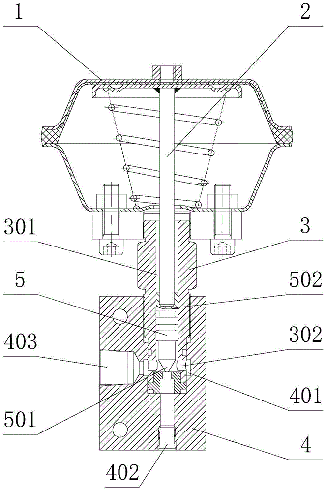
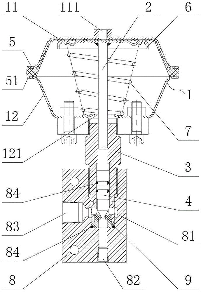
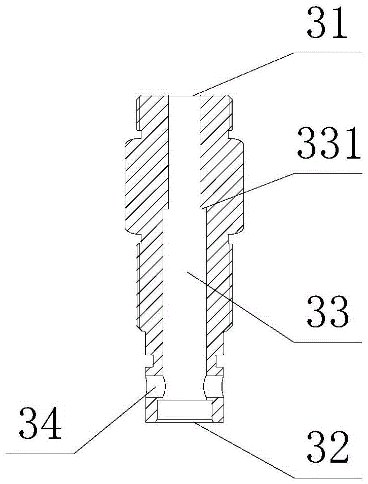
[0021] Such as figure 2 with image 3 As shown, the embodiment of the present invention provides a pneumatic shut-off valve, including: a pneumatic housing 1, a push rod 2, a valve sleeve 3 and a valve core 4, the valve sleeve 3 includes a first end 31 and a second end 32, and the valve sleeve An axial through hole 33 communicating with the first end 31 and the second end 32 is provided between the first end 31 and the second end 32 of the valve sleeve, and a radial through hole 34 communicating with the axial through hole 33 is also provided on the valve sleeve. , the ejector rod 2 extends from the pneumatic casing 1 through the first end 31 into the axial through hole 33 of the valve sleeve 3 , the valve core 4 is arranged in the axial through hole 33 of the valve sleeve 3 , and the valve core 4 is located on the ejector rod 2 Between the...


PUM


Abstract

The invention discloses a pneumatic stop valve and relates to the technical field of valves. Pneumatic shells, ejector rods, valve elements and other components of pneumatic stop valves are prevented from being seriously damaged and even flied off when the pneumatic stop valves bear high-pressure fluid pressure, and object strike accidents are avoided. The pneumatic stop valve comprises a pneumatic shell, an ejector rod, a valve sleeve and a valve element, an axial through hole is formed between the first end and the second end of the valve sleeve, a radial through hole communicated with the axial through hole is formed in the valve sleeve, the ejector rod stretches into the axial through hole of the valve sleeve from the pneumatic shell through the first end, the valve element is arranged in the axial through hole of the valve sleeve, the valve element is located between the ejector rod and the second end, the valve element is connected with the valve sleeve in a sliding seal mode, a limiting structure allowing the ejector rod to pass but prevent the valve element from passing is arranged in the axial through hole of the valve sleeve, the limiting structure is located between the first end and the radial through hole, and the valve element is located between the limiting structure and the second end; the distance between the end, away from the valve sleeve, of the pneumatic shell and the limiting structure is larger than the length of the ejector rod.

Description

technical field [0001] The invention relates to the technical field of valves, in particular to a pneumatic shut-off valve. Background technique [0002] Pneumatic cut-off valves are often used in high-pressure medium pipelines or devices to cut off the medium. It controls high-pressure fluid through low-pressure gas, and can realize remote control in a timely and effective manner to ensure tight sealing. [0003] Such as figure 1 As shown, the existing pneumatic globe valve includes a pneumatic housing 1, a push rod 2, a valve sleeve 3, a valve body 4 and a valve core 5, the valve body 4 has a valve cavity 401, an inlet 402 and an outlet 403, and the inlet 402 is perpendicular to the outlet 403 The valve sleeve 3 has an axial through hole 301 and a radial through hole 302 communicating with the axial through hole. The radial through hole 302 communicates with the valve cavity 401. Extending into the axial through hole 301 of the valve sleeve 3, the spool 5 is located in t...

Claims


Application Information

Patent Timeline
Patent Type & Authority Patents(China)
IPC IPC(8): F16K1/00F16K1/32F16K31/126
CPCF16K1/00F16K1/32F16K31/1262
Inventor 王立志刘洋李旭东王君明王玉金
Owner 四川安东油气工程技术服务有限公司
Why Eureka
Try Eureka