Internal thread perpendicularity detecting device and using method thereof
A detection device and technology for verticality, applied to the field of internal thread verticality detection devices, can solve the problems of easy scratching of workpieces, high false detection frequency, low detection accuracy, etc., so as to improve operability and economy, and reduce detection Difficulty, the effect of solving technical problems
- Summary
- Abstract
- Description
- Claims
- Application Information
AI Technical Summary
Problems solved by technology
Method used
Image
Examples
Embodiment 1
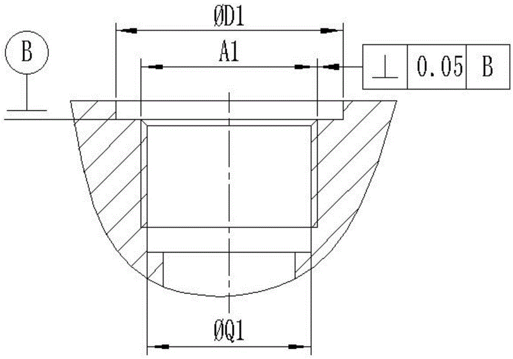
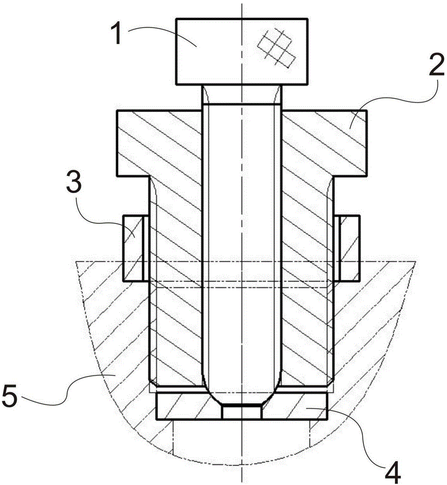
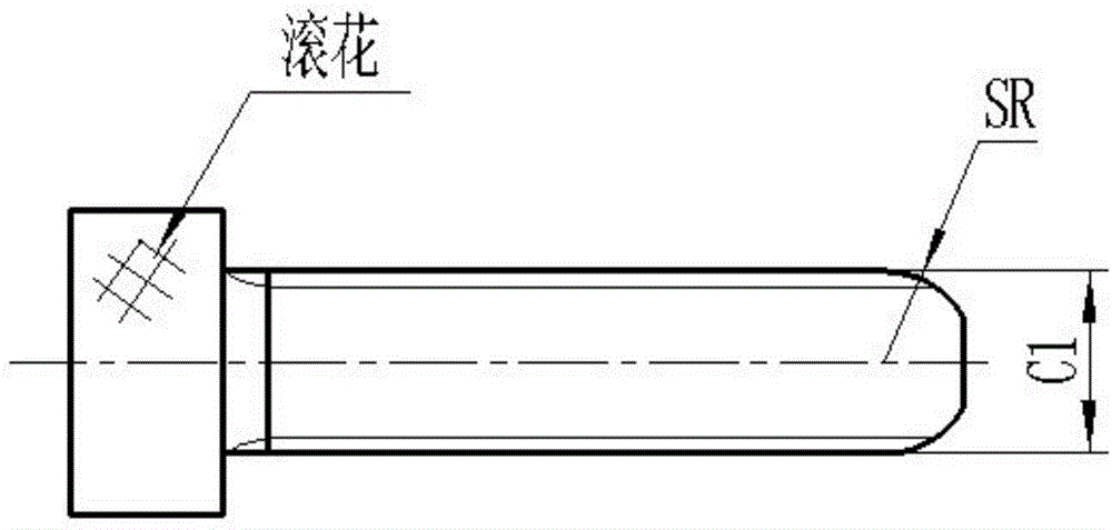
[0041]During detection, screw 1 is inserted into the threaded hole C2 opened in the middle of threaded sleeve 2 through external thread C1, the end of screw 1 does not exceed the lower end surface of threaded sleeve 2, and the distance between the end surface of screw 1 and the lower end surface of threaded sleeve 2 is 0mm, that is, the end surface of the screw 1 is flush with the lower end surface of the threaded sleeve 2; put the backing plate 4 into the φQ1 at the bottom of the threaded hole A1 on the workpiece 5 to be tested, and then put the reference block 3 into the φD1 on the workpiece 5 to be measured In the step hole; screw the assembly assembly of screw 1 and threaded sleeve 2 into the internal threaded hole of the workpiece 5 through the external thread A2, and ensure that there is a gap of 1 mm between the bottom end surface of the threaded sleeve 2 and the bottom end surface of the internal threaded hole A1 ; Rotate the screw 1 so that the ball head SR at the end ...
Embodiment 2
[0043] During detection, screw 1 is inserted into the threaded hole C2 opened in the middle of threaded sleeve 2 through external thread C1, the end of screw 1 does not exceed the lower end surface of threaded sleeve 2, and the distance between the end surface of screw 1 and the lower end surface of threaded sleeve 2 is 2mm; put the backing plate 4 into the φQ1 at the bottom of the threaded hole A1 on the workpiece 5 to be tested, and then put the reference block 3 into the stepped hole of φD1 on the workpiece 5 to be tested; put the screw 1 and the screw sleeve 2 assembly assembly Screw the external thread A2 into the internal thread hole of the workpiece 5 to be tested, and ensure that there is a gap of 2 mm between the bottom end surface of the threaded sleeve 2 and the bottom end surface of the internal thread hole A1; rotate the screw 1 so that the ball head SR at the end is inserted into the backing plate 4 In the tapered hole opened in the middle of the top, then tighten...
Embodiment 3
[0045] During detection, screw 1 is inserted into the threaded hole C2 opened in the middle of threaded sleeve 2 through external thread C1, the end of screw 1 does not exceed the lower end surface of threaded sleeve 2, and the distance between the end surface of screw 1 and the lower end surface of threaded sleeve 2 is 1mm; put the backing plate 4 into the φQ1 at the bottom of the threaded hole A1 on the workpiece 5 to be tested, and then put the reference block 3 into the stepped hole of φD1 on the workpiece 5 to be tested; Screw the external thread A2 into the internal thread hole of the workpiece 5 to ensure that there is a gap of 1.5 mm between the bottom end surface of the threaded sleeve 2 and the bottom end surface of the internal thread hole A1; rotate the screw 1 so that the ball head SR at the end is inserted into the pad Then tighten the screw 1 in the tapered hole opened in the middle of the top of the plate 4; use a caliper or an outer micrometer to measure the ga...
PUM
 Abstract
Description
Claims
Application Information
 - R&D
- Intellectual Property
- Life Sciences
- Materials
- Tech Scout
- Unparalleled Data Quality
- Higher Quality Content
- 60% Fewer Hallucinations
Browse by: Latest US Patents, China's latest patents, Technical Efficacy Thesaurus, Application Domain, Technology Topic, Popular Technical Reports.
© 2025 PatSnap. All rights reserved.Legal|Privacy policy|Modern Slavery Act Transparency Statement|Sitemap|About US| Contact US: help@patsnap.com


