Polarization Control Method Used in Wavefront Reference Source of Fiber Point Diffraction Interferometer

A point-diffraction interference and polarization control technology, applied in optics, instruments, optical components, etc., to achieve the effect of improving the control speed and avoiding blindness

Active Publication Date: 2017-02-01
CHANGCHUN INST OF OPTICS FINE MECHANICS & PHYSICS CHINESE ACAD OF SCI
View PDF4 Cites 0 Cited by
  • Summary
  • Abstract
  • Description
  • Claims
  • Application Information

AI Technical Summary

Problems solved by technology

[0003] The present invention aims to solve the technical problems in the prior art and meet the requirements of the point diffraction interferometer used in extreme ultraviolet lithography optical detection for the circular polarization state of the diffracted wavefront, that is, to quickly realize the circular polarization state without introducing additional errors Regulation, providing a polarization control method used in the wavefront reference source of the fiber point diffraction interferometer

Method used


Image

  • Polarization Control Method Used in Wavefront Reference Source of Fiber Point Diffraction Interferometer
  • Polarization Control Method Used in Wavefront Reference Source of Fiber Point Diffraction Interferometer
  • Polarization Control Method Used in Wavefront Reference Source of Fiber Point Diffraction Interferometer

Examples


Embodiment Construction
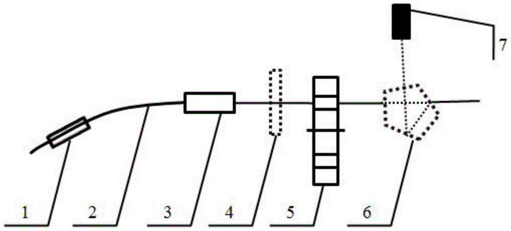
[0025] The inventive idea of ​​the present invention is: the technical idea of ​​the present invention is to change the polarization state of the optical fiber diffracted beam through a polarization controller, and then use a circularly polarized light detection system to detect the polarization state of the beam. The difference is that the polarization state of the initial beam is used The theoretical calculation of the rotating polarizer method, and then the voltage required to control the two channels of the polarization controller to reach the circular polarization state is calculated. Based on the fine adjustment of the theoretical calculation, the other two control voltages are fine-tuned, and the circular polarization state is finally obtained. The polarization control system is conveniently moved out of the optical path, so that no additional errors are introduced.

[0026] Theoretical calculation method:

[0027] Theoretical analysis of the degree of freedom of the control...


PUM


Abstract

The invention relates to a polarization control method used in the wave surface reference source of a fiber point diffraction interferometer. The spherical wave diffracted by a fiber is collimated by a high-quality collimating lens, and then passes through a rotatable polarizer placed on a single-axis displacement stage, and is placed in a pass through A double-layer density disk with a hole, a pentaprism placed on a uniaxial translation stage and an optical power meter, the polarization state of the initial beam can be determined by theoretical calculation using a rotatable polarizer; then the rotatable polarizer is moved out with a uniaxial translation In the optical path, turn the double-layer density disk to the circularly polarized light detection state, that is, 1 / 4 wave plate + polarizer, use the initial beam polarization state obtained in the previous step to calculate the control voltage of the two control channels of the polarization controller, and then fine-tune, The circular polarization state can be obtained by observing the reading of the optical power meter until the extinction. This system can realize the rapid adjustment of the circular polarization state without introducing additional errors to the wavefront reference source, and can effectively improve the contrast and detection accuracy of interference fringes.

Description

Technical field [0001] The invention belongs to the field of polarization control of the wavefront reference source of a point diffraction interferometer, and specifically relates to a polarization control method used in the wavefront reference source of an optical fiber point diffraction interferometer. Background technique [0002] Extreme ultraviolet lithography (EUVL) technology is considered to be one of the most promising next-generation lithography technologies. It uses 13.5nm extreme ultraviolet light to image the pattern on the mask on a silicon wafer coated with photoresist. In order to achieve the resolution of the diffraction limit of the projection optical system, according to the Marachel criterion, the system wave aberration is required to be less than λ / 14, that is, 1nm RMS. Therefore, the projection system wave aberration detection device must achieve sub-nanometer accuracy. The traditional interference The detection method has been unable to achieve high-precisi...

Claims


Application Information

Patent Timeline
Patent Type & Authority Patents(China)
IPC IPC(8): G02B27/28G03F7/20
CPCG02B27/286
Inventor 金春水代晓珂
Owner CHANGCHUN INST OF OPTICS FINE MECHANICS & PHYSICS CHINESE ACAD OF SCI
Why Eureka
Try Eureka