
A liquid cooling chip for high power semiconductor laser

A refrigeration chip and semiconductor technology, which is applied to semiconductor lasers, lasers, laser parts, etc., can solve problems such as restricting the improvement of semiconductor laser power and application fields, affecting the reliability of semiconductor lasers, and reducing device life and reliability. Simple, high reliability, and the effect of reducing production costs

Active Publication Date: 2018-02-02
FOCUSLIGHT TECH
View PDF7 Cites 0 Cited by
  • Summary
  • Abstract
  • Description
  • Claims
  • Application Information

AI Technical Summary

Problems solved by technology

For high-power semiconductor lasers, conduction cooling is used, and the heat dissipation efficiency is low, which will lead to a decrease in device life and reliability, and generally can only reach an output power of tens of watts; if micro-channel liquid cooling is used, the cooling liquid Need to use high-quality deionized water, the cost is high, and long-term use will cause corrosion or blockage of the microchannel wall, which seriously affects the reliability of the semiconductor laser
[0004] Chinese patent 200910023753.3 proposes a liquid cooling chip structure, although it solves the problem of tube wall blockage of microchannel liquid cooling, but the heat dissipation effect needs to be improved, which restricts the further improvement of the power and application fields of semiconductor lasers

Method used


Image

  • A liquid cooling chip for high power semiconductor laser
  • A liquid cooling chip for high power semiconductor laser
  • A liquid cooling chip for high power semiconductor laser

Examples


Embodiment Construction

[0032] Describe the present invention in detail below in conjunction with accompanying drawing and specific implementation example:

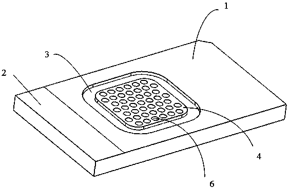
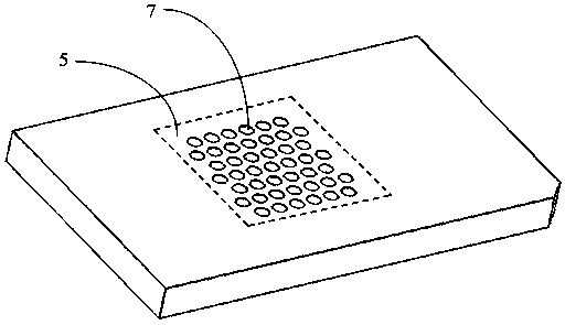
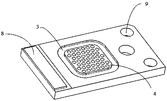
[0033] figure 1 It is a structural schematic diagram of the liquid cooling sheet of the present invention, a liquid cooling sheet for high-power semiconductor lasers includes a cooling sheet main body 1, and the cooling sheet main body is a chip structure, and the sheet structure includes an upper surface and a lower surface; the cooling sheet The main body 1 is provided with a water passage area and a chip installation area 2, and the chip installation area 2 is located at one end of the liquid cooling chip main body 1, where the laser chip is installed; the water passage area is located on the cooling chip main body 1 close to the chip installation area 2 ; The water passage area of ​​the main body of the refrigeration sheet is divided into A surface 4 and B surface 5 corresponding to each other. The A surface 4 and the B surface 5 are respect...


PUM


Abstract

The present invention proposes a liquid refrigerating sheet for high-power semiconductor lasers, especially a macro-channel type liquid refrigerating sheet. The main body of the cooling chip is a chip-mounted structure, with a water passage area and a chip installation area on it. The chip installation area is located at one end of the liquid cooling chip main body, where the laser chip is installed; the water passage area is located on the cooling chip main body near the chip installation area. Position; the water passage area of ​​the main body of the refrigeration sheet is divided into A and B faces which correspond to each other, and the A and B faces are respectively located on the upper and lower surfaces of the sheet-shaped refrigeration sheet main body, and the A face of the water passage area is provided with a plurality of water outlet columns The holes C and B are provided with a plurality of water inlet column holes D; the water outlet column holes C on the A side communicate with the water inlet column holes D on the B side. The present invention has a simple structure, no complex structure of micro-channels, adopts through holes, does not require high particle size of the refrigerant liquid, and has a low risk of corrosion of the liquid refrigerant passages, and can improve the reliability of the entire semiconductor laser device during use. .

Description

technical field [0001] The invention belongs to the field of laser manufacturing, and relates to a liquid cooling chip used for high-power semiconductor lasers, in particular to a macro-channel liquid cooling chip. Background technique [0002] At present, high-power semiconductor lasers have been widely used in industry, national defense and other fields, with huge market demand and broad development prospects. As the power of the semiconductor laser increases, the thermal diffusion of the matrix material will cause a change in stress. Due to the deposition of heat, the temperature of the semiconductor laser chip will increase and the output wavelength will change, making the semiconductor laser unable to work normally. In order to improve the power, reliability and performance stability of semiconductor lasers and reduce production costs, an efficient heat dissipation structure must be designed. Therefore, it is necessary to design and manufacture low-cost and high-effici...

Claims


Application Information

Patent Timeline
Patent Type & Authority Patents(China)
IPC IPC(8): H01S5/024
Inventor 梁雪杰宗恒军王警卫刘亚龙刘兴胜
Owner FOCUSLIGHT TECH
Learn More