A head light massage instrument

A head and instrument technology, applied in the field of head light massage equipment, can solve the problems of difficult operation, complex operation, and low positioning accuracy, and achieve the effects of reducing operation difficulty, simplifying operation process, and improving user experience

Active Publication Date: 2016-03-09
张顺清 +1
4 Cites 0 Cited by

AI-Extracted Technical Summary

Problems solved by technology

[0003] At present, in the process of He-Ne laser irradiation using existing instruments, especially in the process of He-Ne laser irradiation on the patient's head, the operation of locating the irradiated part is quite complicated, the operation is very difficult and the positioning accuracy is not high
Moreover, in order to prevent the deviation of the irradiation position, the patient nee...

Method used

[0075] A plurality of laser emitters for outputting laser light are constructed in the illuminator 100 of the present embodiment. It is not difficult to understand that each laser transmitter needs a laser input, which requires a matching light source for each laser transmitter. In order to simplify the hardware structure and reduce the hardware cos...

Abstract

The invention discloses a head illumination massage apparatus, which comprises a positioning frame, an illuminator and a laser generator, wherein the positioning frame is constructed to be wearable on the head of a user and comprises a fixing member; the fixing member is used for fixing the positioning frame on the head of the user when the user wears the positioning frame; the illuminator is installed on the positioning frame and used for laser irradiation at a specific position of the head of the user; the laser generator is connected with the illuminator and used for generating helium-neon laser so as to provide a light source for the laser irradiation for the illuminator. The head illumination massage apparatus cannot only realize the laser positioning during helium-neon laser irradiation conveniently and rapidly, but also can realize multiple illumination massage modes flexibly on the basis of specific needs of the user, so as to improve the illumination massage effect and the user experience on the basis of simplifying the operation process and reducing the operation difficulty.

Application Domain

Vibration massageRadiation therapy

Technology Topic

EngineeringLight source +3

Image

  • A head light massage instrument
  • A head light massage instrument
  • A head light massage instrument

Examples

  • Experimental program(1)

Example Embodiment

[0038] The implementation of the present invention will be described in detail below in conjunction with the accompanying drawings and examples, so that implementers of the present invention can fully understand how the present invention uses technical means to solve technical problems, and achieve the realization process of technical effects and according to the above-mentioned realization process The present invention is implemented concretely. It should be noted that, as long as there is no conflict, each embodiment and each feature in each embodiment of the present invention can be combined with each other, and the formed technical solutions are all within the protection scope of the present invention.
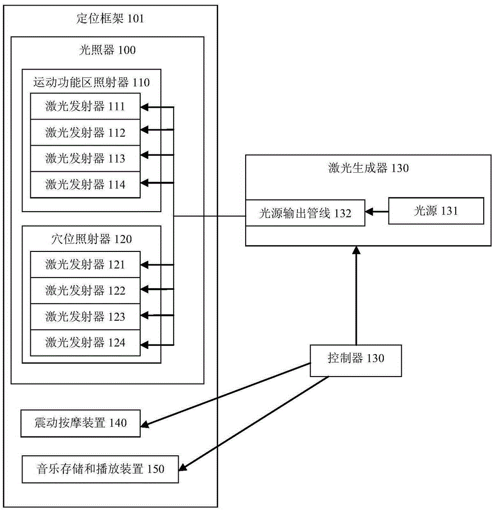
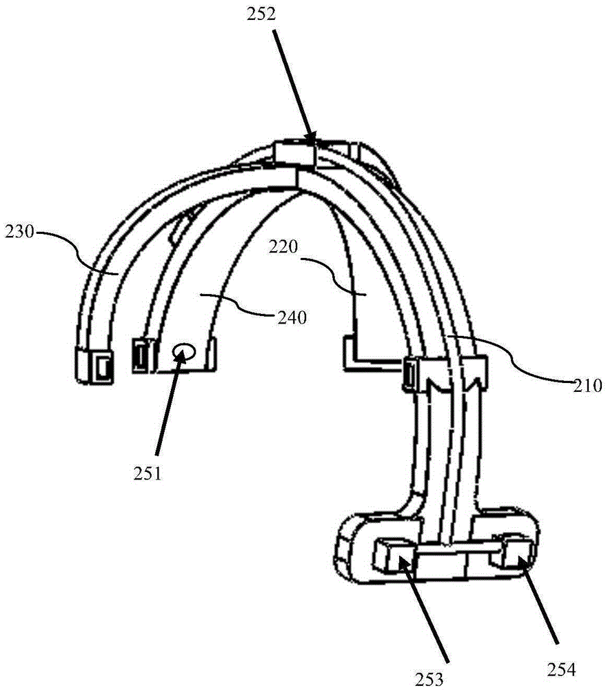
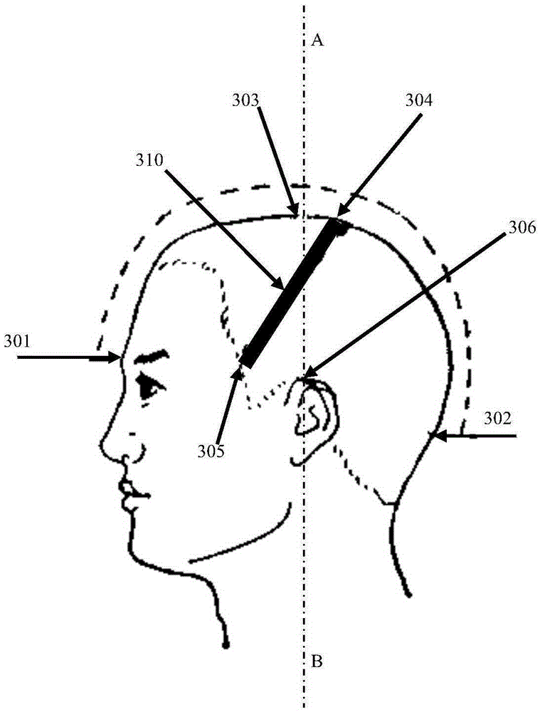
[0039] The invention provides a head light massage instrument, the main purpose of which is to simply and quickly realize laser irradiation on a specific position of a user's head by using a helium-neon laser. like figure 1 As shown, the apparatus of this embodiment includes an illuminator 100 for irradiating a specific position of the user's head with a HeNe laser. To irradiate the specific skin of the user's head, it is first necessary to ensure that the He-Ne laser output by the illuminator 100 is irradiated on the target skin. That is to say, it is necessary to precisely locate the irradiation area of ​​the He-Ne laser.
[0040] Usually, to locate the irradiated area of ​​the He-Ne laser, the user's head must first be fixed, and then the illuminator 100 is fixed at a specific position near the user's head and the laser emission angle of the illuminator 100 is adjusted so that the helium emitted by the illuminator 100 Neon laser light shines on a specific location on the user's head. The whole process is quite cumbersome and has great operational difficulty. Especially when fixing the user's head and illuminator, it will bring great discomfort to the user.
[0041] One of the main inventive points of the present invention is to simplify the irradiation positioning steps. In order to achieve the above-mentioned goals, a positioning frame 101 is constructed in the instrument of the present invention, the positioning frame 101 is configured to be worn on the user's head, and the positioning frame 101 includes a fixing member, and the fixing member is used for when the user wears the positioning frame 101 The relative position between the user's head and the positioning frame 101 is fixed at the same time. figure 2 What is shown is a schematic diagram of the appearance of the positioning frame according to an embodiment of the present invention. like figure 2 As shown, the positioning frame is configured as a claw structure, which includes four fixing members 210 , 220 , 230 and 240 for fixing. When worn, the user's head is surrounded by four fixing members 210, 220, 230 and 240. The fixing member 210 is located at the position of the user's head along the back of the head to the occipital bone, and the fixing member 240 is located at the user's head along the forehead. To the position between the eyebrows, the fixing member 220 and the fixing member 230 are respectively located on both sides of the user's head.
[0042]The illuminator 100 is installed on the positioning frame 101 , and the laser emission port of the illuminator 100 is fixed at a specific position on the positioning frame 101 . The positioning frame 101 fixedly worn relative to the user's head cannot move, so the position of the laser emission port of the illuminator 100 is determined and unchanged relative to the user's head. The installation position of the laser emitter on the positioning frame 101 is determined in advance based on user requirements, so that the positioning frame 101 only needs to be worn every time the instrument is used, and the position of the laser emitter does not need to be adjusted again. In this way, the positioning of the irradiation site during the He-Ne laser irradiation process can be realized conveniently and quickly, which not only greatly simplifies the operation process and reduces the difficulty of operation, but also improves the positioning accuracy and precision.
[0043] In order to further ensure that the positioning frame 101 can be fixed (its relative position does not change) to be worn on the user's head, and to improve wearing comfort, the fixing member of this embodiment also includes a head circumference elastic adjustment belt (fastening) that plays an auxiliary fixing role. volume), which not only improves the fixing degree of the positioning frame 101, but also greatly improves the comfort level of the user and improves the user experience.
[0044] Of course, when different users wear the positioning frame 101 , the relative positions of the positioning frame 101 and the head cannot be guaranteed to be exactly the same. In this embodiment, the positioning frame 101 includes an adjustable connector, and the laser emission port in the illuminator 100 is installed on the positioning frame 101 through the adjustable connector. The adjustable connecting piece is used to adjust the position of the laser emission port and the emission angle of the He-Ne laser emitted by the laser emission port, so as to ensure that the He-Ne laser can be accurately irradiated on the target skin.
[0045] In addition, the essence of the present invention is to use the He-Ne laser to irradiate the user's brain. For the convenience of description and positioning, the specific position of the user's head skin is used to determine the irradiation target of the He-Ne laser. In order to ensure that the helium-neon laser can penetrate the skin and act on the specific position of the brain as expected. In this embodiment, when all the laser emitting ports are installed on the positioning frame 101 , they are configured so that the emitted HeNe laser is perpendicular to the irradiated skin surface.
[0046] In actual use, there is more than one area of ​​the user's head that needs to be irradiated with laser light. In this embodiment, corresponding irradiation modules are constructed in the illuminator 100 for different areas of the user's head. Each irradiation module includes one or Multiple laser launch ports. One of the purposes of the instrument of the present invention is to irradiate the motor function area of ​​the cerebral cortex of the user with a helium-neon laser. Therefore if figure 1 As shown, in this embodiment, the illuminator 100 includes a motor function zone illuminator 110 . When the positioning frame 101 is normally fixed and worn on the user's head, the irradiated area of ​​the user's head skin by the motor function area illuminator 110 corresponds to the user's cerebral cortex motor function area.
[0047] For the convenience of description, the motion function zone illuminator 110 on the positioning frame 101 will be described based on the description of the irradiation area of ​​the sports function zone illuminator 110 on the skin of the user's head when the positioning frame 101 is normally fixed and worn on the user's head. fixed position.
[0048] The corresponding areas of the motor function area of ​​the cerebral cortex on the user's skin are two strip-shaped areas. Two long strips are located symmetrically on either side of the head. image 3 The area 310 marked in the illustration is a strip-shaped area on one side of the user's head. The area 310 corresponds to the corresponding area of ​​the motor function area of ​​the cerebral cortex on the skin on one side of the user's head. The lower end of region 310 is located at the intersection of the brow-occipital line and the front edge of the temples on both sides of the user's head (point 305). The upper end of region 310 is located at point 304, which is located 0.5 cm behind the midpoint (point 303) of the line connecting the brow center (point 301) and the occipital tuberosity (point 302) on the midline of the user's head.
[0049] Considering the determination process of point 304 and point 305 and the differences in specific conditions such as different users' head shapes, the positions of point 304 and point 305 have certain uncertainties (for example, usually the brow-occipital line on both sides of the user's head and The point where the leading edges of the sideburns intersect is a range rather than a precise point). Therefore, in order to make the region 310 more accurately correspond to the motor function area of ​​the cerebral cortex, fine-tuning of the region 310 is required. In a three-dimensional view, the connecting point 304 and the point 305 are an arc, and there is another arc corresponding to it on the other side of the head, and the connecting point of the two arcs is the point 304 . Adjusts the two arcs symmetrically so that both arcs lie in the same plane.
[0050] In a stereoscopic view, the line connecting the crowns of the two ears on the head is a line that connects the crowns of the two ears (point 306 ) along the scalp and directly above the top of the head. The line connecting the coronals of the ears to the head defines a plane that is perpendicular to the anterior-posterior longitudinal direction of the head. Reflected in image 3 That is, the plane that passes through the straight line AB perpendicular to the paper (the straight line AB is perpendicular to the horizontal plane). Continue to fine-tune the above two arcs (the arc determined by point 305 and point 304 and the corresponding arc on the other side of the head), so that the plane defined by the two arcs is the same as the plane defined by the coronal line between the two ears of the head. The angle between the planes is 30 degrees.
[0051] At the same time, for different people, the width of the corresponding strip-shaped area of ​​the motor function area of ​​the cerebral cortex on the head is also different. In this embodiment, the width of the strip-shaped area is set to 0.2-0.5 mm (the specific value is determined based on the specific situation of the user). Finally, take the fine-tuned two arcs as the center line, and use a certain value in 0.2-0.5 millimeters (determining the specific value based on the specific situation of the user) as the width to construct the region 310 and the corresponding region on the other side of the head.
[0052] In this embodiment, when the positioning frame is normally fixed and worn on the user's head, the irradiated area of ​​the skin of the user's head by the sports function area illuminator 110 is consistent with the area 310 and the corresponding area on the other side of the head. .
[0053] Since the motor function area of ​​the cerebral cortex is divided into several parts based on its specific functions, in order to achieve different therapeutic purposes, it is necessary to adjust a specific area or any of the two long strips according to the needs of the user. Laser irradiation is performed on a specific area range in the shaped area. In order to achieve the above-mentioned purpose, the motion function area illuminator 110 includes multiple laser emitters, each laser emitter includes a laser emission port, different laser emitters have different irradiation areas, and each laser emitter includes an independent control switch . The motor function zone irradiator 110 of this embodiment is configured to independently control different laser emitters according to the needs of the user, so as to irradiate one or more areas on the skin of the user's head with laser light.
[0054] Because the corresponding area of ​​the cerebral cortex motor function area on the user's skin is a strip-shaped area, in order to make the irradiation area of ​​the motor function area illuminator 110 on the user's head skin more perfect and the cerebral cortex motor function area on the user's skin The corresponding areas above are consistent, and the laser emitters in the sports function zone illuminator 110 are rectangular head laser emitters. When the instrument works normally, the irradiation area of ​​the rectangular head laser emitter on the skin of the user's head is rectangular.
[0055] In this embodiment, the motor function area of ​​the cerebral cortex is divided into two parts based on the control of the left and right halves of the limbs, and at the same time, each part is further divided into two regions based on the control of limb and trunk movement and facial movement control, that is, the whole Divided into 4 areas. For the long strips on either side of the head:
[0056] The lower part of the corresponding strip area accounts for 1/3 of the total length of the strip area;
[0057] The trunk movement control corresponds to the upper part of the strip area, which accounts for 2/3 of the total length of the strip area.
[0058] Correspondingly, the sports function zone illuminator 110 includes four laser transmitters 111, 112, 113 and 114, wherein:
[0059] The irradiation areas of the laser emitters 111 and 112 on the skin of the user's head correspond to the lower part of the two elongated areas, which account for 1/3 of the total length of each elongated area;
[0060] The irradiation areas of the laser emitters 113 and 114 on the skin of the user's head respectively correspond to the upper part of the two elongated areas, accounting for 2/3 of the total length of each elongated area.
[0061] In order to expand the function and improve the treatment effect, such as figure 1 As shown, the instrument of this embodiment is also configured with an acupoint irradiator 120 for the acupoints on the head. When the positioning frame 101 is normally fixed and worn on the user's head, the irradiation area of ​​the acupoint irradiator corresponds to a specific acupoint on the user's head. In this embodiment, the acupoint irradiator 120 is configured with multiple laser emitters, each laser emitter includes a laser emission port and each laser emitter corresponds to a specific acupoint. The specific acupoints mentioned above include Shangxing, Baihui, Sishencong and bilateral Fengchi. Of course, in other embodiments of the present invention, other acupoints can be selected according to actual needs.
[0062] Similar to the laser emitters in the exercise function zone irradiator 110, each laser emitter in the acupuncture point irradiator 120 includes an independent control switch. The acupoint irradiator 120 of this embodiment is configured to independently control different laser emitters according to the needs of the user, so as to perform laser irradiation on one or more acupoints on the skin of the user's head.
[0063] Since the corresponding area of ​​the acupuncture point on the skin can be regarded as a dot, in this embodiment, the laser emitter in the acupuncture point illuminator 120 is a round laser emitter. When the instrument is working normally, the circular head laser emitter is a circular light spot on the irradiation area of ​​the user's head skin. In this embodiment, laser emitters 121, 122, 123 and 124 are configured for Shangxing, Baihui, Sishencong and bilateral Fengchi points, wherein:
[0064] The laser emitter 121 is corresponding to the star point, installed in such as figure 2 In the position of 251 shown;
[0065] The laser emitters 123 and 124 correspond to the Fengchi points on both sides respectively, and are respectively installed in such as figure 2 In the positions of 253 and 254 shown;
[0066] The laser emitter 122 corresponds to Baihui and Sishencong points, and is installed in such as figure 2 252 shown in the position.
[0067] Baihui acupoint and Sishencong acupoint correspond to the same irradiated area with a diameter of 3 cm, and the diameter of the irradiated area corresponding to Shangxing acupoint or bilateral Fengchi acupoint is 1 cm.
[0068] In order to further improve the therapeutic effect, expand the functions, and play an auxiliary role in He-Ne laser irradiation, the instrument of this embodiment also includes a vibration massage device 140 , which is installed on the positioning frame 101 . In order to avoid affecting the relative positional relationship between the positioning frame 101 and the user's head, the vibration massage device 140 is configured to massage the skin of the user's head vertically. Considering the massage effect and user experience, the vibration amplitude of the vibration massage device 140 is less than 2mm.
[0069] In order to perform targeted auxiliary massage, the vibration massage device 140 in this embodiment is configured to massage the peripheral skin of the irradiation area of ​​the motor function illuminator 110 . Figure 4 Shown is the vibration massage plate of the vibration massage device 140 of this embodiment. A strip-shaped through-hole 402 is formed in the center of the vibrating massage board, and the shape and size of the strip-shaped through-hole 402 are consistent with the irradiation area in the motion function area illuminator 110 . When working normally, the vibrating massage board is pressed by the positioning frame 101 to the specified position on the skin of the user's head, and the elongated through hole 402 just corresponds to the irradiated area of ​​the illuminator 110 in the exercise function area.
[0070] A plurality of button-type vertical vibrators (such as 401) are constructed on the vibration massage board. When the helium-neon laser emitted by the motion function area illuminator 110 irradiates the skin of the user's head through the elongated through hole 402, the button-type vertical vibrator (such as 401) on the vibrating massage board promptly radiates the skin around the irradiation area. Vertical massage.
[0071]In order to further improve pertinence, the vibration massage device 140 includes a plurality of vibration massage units with independent control switches, and each vibration massage unit corresponds to a laser emitter in the motion function area illuminator 100 (in this embodiment, the laser emitter 111, 112, 113 or 114). specific to Figure 4 , each vibration massage unit contains a part of the button-type vertical vibrator. When the helium-neon laser emitted by a certain laser emitter in the motion function zone illuminator 110 irradiates the skin of the user's head through the strip-shaped through hole 402, the button-type vertical vibrator (such as 401) of the corresponding vibration massage unit is Massage the skin vertically around the irradiated area.
[0072] Simultaneously, in order to further improve the therapeutic effect and expand the functions, the instrument of this embodiment also includes a music storage and playing device 150 . The music storage and playback device 150 is used to play music to the user while performing the light massage, so as to relieve the user's spirit and achieve a better light massage effect.
[0073] like figure 1 Shown in this embodiment, the laser emitters 111, 112, 113 and 114 are installed on the fixing members 230 and 220; the vibration massage device 140 is installed on the fixing members 230 and 220; the laser emitter 121 is installed on the fixing members 240 ; The laser emitters 123 and 124 are installed on the fixing member 210 . It is not difficult to understand that the fixing members 210 , 220 , 230 and 240 not only play the role of fixing the positioning frame 101 when the user wears the positioning frame 101 , but also play the role of positioning the laser emitter. This design greatly simplifies the structure of the positioning frame 101 and reduces hardware costs. Of course, in other embodiments of the present invention, other structures may be used to construct the positioning frame 101 , such as constructing an independent fixing member.
[0074] It is not difficult to understand that a corresponding light source is required for HeNe laser irradiation. Therefore if figure 1 As shown, the instrument of this embodiment further includes a laser generator 130 , which is connected to the illuminator 100 and is used to generate a HeNe laser to provide the illuminator 100 with a light source for laser irradiation.
[0075] A plurality of laser emitters for outputting laser light are built in the illuminator 100 of this embodiment. It is not difficult to understand that each laser transmitter needs a laser input, which requires a matching light source for each laser transmitter. In order to simplify the hardware structure and reduce the hardware cost, the laser generator 130 includes a light source output pipeline 132 and a light source 131 . The light source 131 is connected to all laser emitters through the light source output pipeline 132 . In this way, only one light source is needed to provide light sources for all laser emitters, greatly reducing hardware requirements and hardware costs.
[0076] In this embodiment, the He-Ne laser is mainly used to irradiate the specific skin of the user's head so as to achieve the purpose of phototherapy on the user's brain. In order to achieve an optimal lighting effect, the light source 131 is configured to adjust the output He-Ne laser wavelength, laser output power and laser output density according to user's requirements. In this embodiment, the light source 131 is generally set to output a HeNe laser with a wavelength of 632.8 nm at an output power of 2-5 mw.
[0077] The laser emitters in the instrument of this embodiment all include independent control switches, and the user can independently control the individual laser emitters according to the needs of use. In order to further meet the needs of users, the instrument of this embodiment also includes a controller 130 connected to a vibration massage device 140 , a laser generator 130 and a music storage and playback device 150 . The controller 130 includes a timer, which is used to control the switches of the vibration massage device 140, the laser generator 130, and the music storage and playback device 150 at any time or at regular intervals according to the user's needs.
[0078] To sum up, the instrument of this embodiment can flexibly implement various light massage modes based on the specific needs of users, thereby improving the effect of light massage on the basis of simplifying the operation process and reducing the difficulty of operation.
[0079] Although the embodiments disclosed in the present invention are as above, the described content is only an embodiment adopted for the convenience of understanding the present invention, and is not intended to limit the present invention. The method described in the present invention can also have other various embodiments. Without departing from the essence of the present invention, those skilled in the art can make various corresponding changes or modifications according to the present invention, but these corresponding changes or modifications should all belong to the protection scope of the claims of the present invention.

PUM

PropertyMeasurementUnit
Wavelength632.8nm

Description & Claims & Application Information

We can also present the details of the Description, Claims and Application information to help users get a comprehensive understanding of the technical details of the patent, such as background art, summary of invention, brief description of drawings, description of embodiments, and other original content. On the other hand, users can also determine the specific scope of protection of the technology through the list of claims; as well as understand the changes in the life cycle of the technology with the presentation of the patent timeline. Login to view more.

Similar technology patents

Call forwarding control method and device

Owner:GUANGDONG XIAOTIANCAI TECH CO LTD

Torpedo modular embedded type cylindrical conformal acoustic base array

InactiveCN106644043AAvoid airtight checksSimplify the operation process
Owner:CSIC NO 710 RES & DEV INST

Precise surfacing welding method of high-hardness cold and hot rolls

InactiveCN105081521Areasonable ideaSimplify the operation process
Owner:HUBEI WANANTONG COMPOSITE REMFG TECH CO LTD

Classification and recommendation of technical efficacy words

  • Reduce the difficulty of operation
  • Simplify the operation process

Method for generating laser cutting program

Owner:GUANGDONG HANS YUEMING LASER GRP CO LTD +1
Why Eureka
Try Eureka