Punching blanking die

A punching blanking, mold technology, applied in the direction of piercing tools, manufacturing tools, metal processing equipment, etc., can solve the problems of inconvenient installation and disassembly, single processed products, high manufacturing cost, etc.

Inactive Publication Date: 2015-04-29
CHANGZHOU INST OF MECHATRONIC TECH
View PDF6 Cites 8 Cited by
  • Summary
  • Abstract
  • Description
  • Claims
  • Application Information

AI Technical Summary

Problems solved by technology

[0002] At present, the widely used punching die is a fixed punching die structure, that is, the punch and forming indenter in the forming device are fastened to the template by the fixing plate through screws and then fixed. The punching die with this structure is not only inconvenient to install and disassemble, but also Moreover, the manufacturing cost is relatively high, and the processed products are single

Method used


Image

  • Punching blanking die
  • Punching blanking die

Examples


Embodiment Construction

[0017] In order to make the content of the present invention more clearly understood, the present invention will be further described in detail below based on specific embodiments and in conjunction with the accompanying drawings.

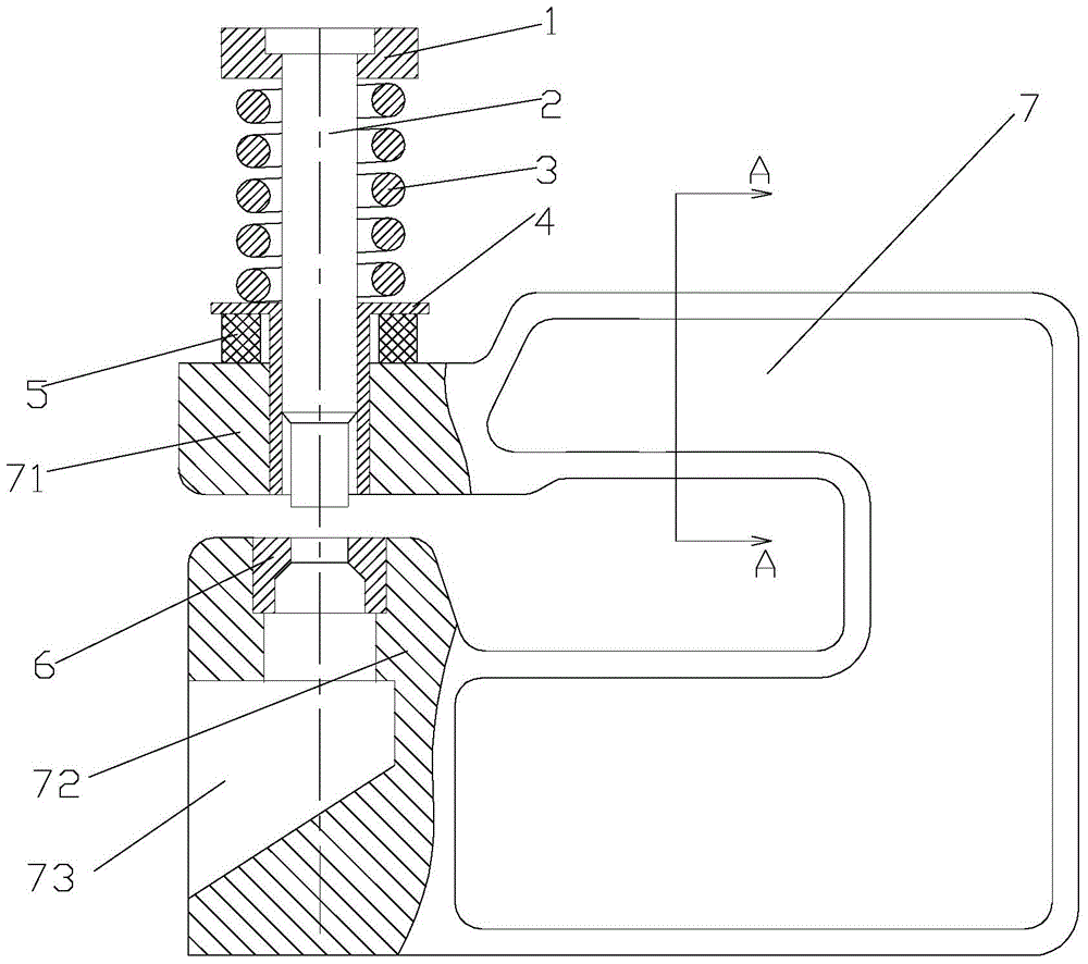
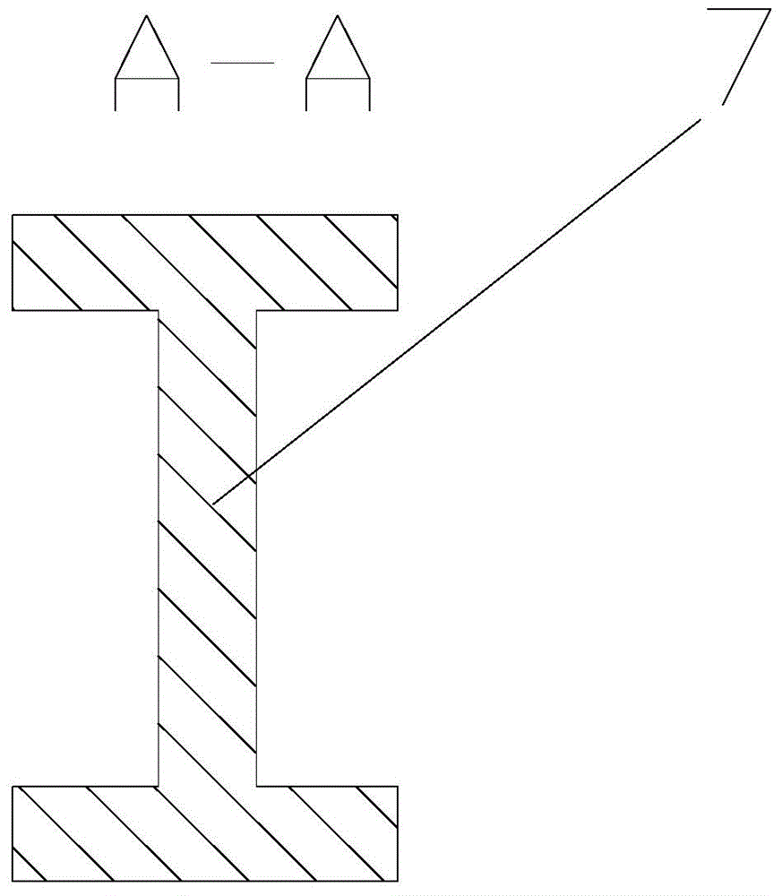
[0018] Such as figure 1 , 2 Shown, a punching blanking die, it includes:

[0019] The mold base 7, the mold base 7 has a punch support part 71 and a die support part 72, and a plate placement area is formed between the punch support part 71 and the die support part 72;

[0020] Embedding die 6, the embedding die 6 is installed on the die supporting part 72 of the mold base 7;

[0021] Punch assembly, the punch assembly has a punch 2, and the punch 2 passes through the punch support part 71 of the die base 7, and the punch 2 can move relative to the punch support part 71, the punch 2 and the embedded die 6 Matching for sheet blanking;

[0022] The return spring 3 is arranged between the punch assembly and the punch support part 71 .

[0023] Su...


PUM


Abstract

The invention discloses a punching blanking die. The punching blanking die comprises a die holder, an embedding cavity die, a punch assembly and a return spring; the die holder is provided with a punch supporting portion and a cavity die supporting portion; a plate arranging area is formed between the punch supporting portion and the cavity supporting portion; the embedding cavity die is installed on the cavity die supporting portion; the punch assembly is provided with a punch; the punch penetrates a punch supporting portion of the die holder; the punch can move relative the punch supporting portion; the punch is matched with the embedding cavity die to enable plate blanking to be convenient; the return spring is arranged between the punch assembly and the punch supporting portion. According to the punching blanking die, the punch can be rapidly replaced, the structure is simple, the operation is simple, the machining is flexible, costs are reduced, products in various types can be punched, the efficiency is high, and the costs are low.

Description

technical field [0001] The invention relates to a punching blanking die. Background technique [0002] At present, the widely used punching die is a fixed punching die structure, that is, the punch and forming indenter in the forming device are fastened to the template by the fixing plate through screws and then fixed. The punching die with this structure is not only inconvenient to install and disassemble, but also And the manufacturing cost is higher, and the processed product is single. Contents of the invention [0003] The technical problem to be solved by the present invention is to overcome the defects of the prior art and provide a punching and blanking die, which can not only quickly replace the punch, but also has a simple structure, easy operation, flexible processing, and reduced cost, and can punch a variety of Specification products, high efficiency and low cost. [0004] In order to solve the above technical problems, the technical solution of the present ...

Claims


Application Information

Patent Timeline
Patent Type & Authority Applications(China)
IPC IPC(8): B21D28/34B21D45/08
CPCB21D28/34B21D45/08
Inventor 冯伟
Owner CHANGZHOU INST OF MECHATRONIC TECH
Why Eureka
Try Eureka