Pipe machining clamp

A technology of clamps and pipe fittings, which is applied in the field of machinery, can solve problems such as loosening and deformation of pipe fittings, and achieve the effect of convenient fixing

Inactive Publication Date: 2015-04-29
CHENGDU KECHUANG JIASI TECH
View PDF8 Cites 9 Cited by
  • Summary
  • Abstract
  • Description
  • Claims
  • Application Information

AI Technical Summary

Problems solved by technology

The clamps that people often use are pressure plates and pads. This kind of clamp is easy to loosen if it is not clamped tightly during cl

Method used


Image

  • Pipe machining clamp

Examples


Example Embodiment

[0010] The present invention will be further described in detail below in conjunction with the accompanying drawings and specific embodiments.

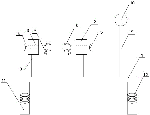
[0011] like figure 1 As shown, a pipe fitting processing jig includes a workbench 1 and two sets of clamps, each set of clamps includes a clamping block 2, the side of the clamping block 2 is provided with a connecting hole, and a sliding sleeve 3 is arranged in the connecting hole , the sliding sleeve 3 is provided with a sliding screw 4, one end of the sliding screw 4 is provided with a handle 5, and the other end is connected with a clamp 6, the clamp 6 is provided with a fastening screw 7, and the clamping block 2 is connected to the support 8 through the The workbench 1 is detachably connected, the pillar 8 is a telescopic sleeve structure, the hoops 6 of the two sets of clips are symmetrically arranged, and the upper surface of the workbench 1 near the edge of one of the short sides is connected to the lighting through a telesco...


PUM


Abstract

The invention discloses a pipe machining clamp. The pipe machining clamp comprises a workbench and two groups of clamping pieces; each group of clamping pieces comprises clamping blocks; the side surface of each clamping block is provided with a connecting hole; a sliding sleeve is arranged in each connecting hole; a sliding screw is arranged in each sliding sleeve; one end of each sliding screw is provided with a handle and the other end of the corresponding sliding screw is connected with a hoop; each hoop is provided with fastening bolts; the clamping blocks are detachably connected with the workbench through support columns; each support column is of a telescopic sleeve structure; the hoops of the two groups of clamping pieces are symmetrically arranged; an illuminating device is connected to the position, close to the edge of one shorter side, of the upper surface of the workbench through a telescopic rod; support legs are arranged on the lower surface of the workbench; each support leg is divided into two sections which are connected by means of a spring. The pipe machining clamp disclosed by the invention is stable and firm to clamp and convenient to operate.

Description

technical field [0001] The invention belongs to the field of machinery, and in particular relates to a pipe fitting processing jig. Background technique [0002] In the processing of pipe fittings, the clamping of pipe fittings is an important procedure. Due to the special shape of the pipe fittings, it is difficult to clamp them. The clamps that people often use are pressure plates and pads. This kind of clamps are easy to loosen if they are not clamped tightly during clamping, but too tight clamping will cause local deformation of the pipe fittings. Now there is no fixture that can easily solve this problem. Contents of the invention [0003] The technical problem to be solved by the present invention is to provide a fixture for processing pipe fittings, which is stable, firm and easy to operate, aiming at the shortcomings of the above-mentioned prior art. [0004] The technical solution adopted in the present invention is: a fixture for processing pipe fittings, incl...

Claims


Application Information

Patent Timeline
IPC IPC(8): B25B11/00B23Q3/06
CPCB25B11/00B25H1/02
Inventor 缪家戌
Owner CHENGDU KECHUANG JIASI TECH
Why Eureka
Try Eureka