Movable elevator

A technology of elevators and lifting lugs, applied in the field of movable elevators, can solve problems such as inconvenient use, achieve the effects of convenient installation, strengthen the structure of the card body, and increase the connection contact area

Inactive Publication Date: 2015-04-29
CHINA NUCLEAR IND 22ND CONSTR
View PDF0 Cites 2 Cited by
  • Summary
  • Abstract
  • Description
  • Claims
  • Application Information

AI Technical Summary

Problems solved by technology

[0002] The single weight of AP1000 steel dome corbel is 2.3 tons. During the production process, it needs to be lifted and turned over many times. Nowadays, ordinary slings are generally used to lift and turn the corbels, but using ordinary slings requires multiple installation adjustments. This has the problem of inconvenient use

Method used


Image

  • Movable elevator

Examples


Embodiment Construction

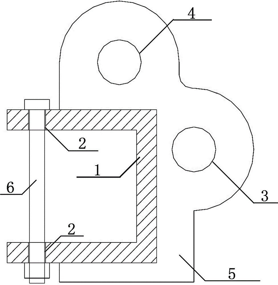
[0016] Such as figure 1 A movable elevator is shown, which includes a sleeve frame 1, which is a three-sided embracing structure, and a bolt hole 2 is provided at the opening of the sleeve frame 1, and horizontal lifting lugs are respectively provided on the outer sides of the two frames connected to the sleeve frame 1 3 and vertical lug 4.

[0017] The three borders of the sleeve frame 1 are perpendicular to each other in pairs at the edges.

[0018] One end of the vertical lifting lug 4 is connected to the L-shaped reinforcing plate 5, the vertical lifting lug 4 is integrated with the horizontal lifting lug 3 and the L-shaped reinforcing plate 5, and the L-shaped reinforcing plate is an L-shaped steel plate.

[0019] The vertical lifting lug 4 , the horizontal lifting lug 3 and the L-shaped reinforcing plate 5 are welded and fixed to the sleeve frame 1 .

[0020] With the above structure, the movable elevator is set on the corbel beam through the sleeve frame 1, then the b...


PUM


Abstract

A movable elevator comprises a nested frame adopting a three-side surrounding structure, wherein bolt holes are formed in the positions of an opening of the nested frame, and a horizontal lifting lug and a vertical lifting lug are arranged on the outer sides of two connected side frames of the nested frame respectively. With adoption of the structure, the nested frame is clamped with a bracket and locked by a bolt through the bolt holes; hoisting and turning work of the bracket can be well completed by means of the horizontal lifting lug and the vertical lifting lug.

Description

technical field [0001] The invention relates to an elevator, in particular to a movable elevator which is convenient for the hoisting and turning of the corbel. Background technique [0002] The single weight of AP1000 steel dome corbel is 2.3 tons. During the production process, it needs to be lifted and turned over many times. Nowadays, ordinary slings are generally used to lift and turn the corbels, but using ordinary slings requires multiple installation adjustments. There is the problem of inconvenient use like this. Contents of the invention [0003] The technical problem to be solved by the present invention is to provide a movable elevator for the deficiencies of the above-mentioned prior art. After it is fixed to the corbel, it can easily carry out the lifting and turning of the corbel only by simple adjustment. Work. [0004] The purpose of the present invention is achieved like this: [0005] The utility model relates to a movable elevator, which includes a s...

Claims


Application Information

Patent Timeline
Patent Type & Authority Applications(China)
IPC IPC(8): B66C1/22
CPCB66C1/22
Inventor 王建峰卓建华董俊杰
Owner CHINA NUCLEAR IND 22ND CONSTR
Why Eureka
Try Eureka