An isolated anti-theft lock structure

An anti-theft lock and isolated technology, which is applied in padlocks, building locks, cylinder locks, etc., can solve the problems of keys not unlocking, shortened service life, and increased user costs

Active Publication Date: 2017-02-22
孟德玉
View PDF5 Cites 0 Cited by
  • Summary
  • Abstract
  • Description
  • Claims
  • Application Information

AI Technical Summary

Problems solved by technology

After a certain period of use, there will be a loose frame between the parts, and even leave traces of key use for thieves, and the anti-theft ability will deteriorate.
In addition, it will shorten the service life and cause problems such as poor flexibility.
It is normal to change the lock cylinder every two or three years for a lock that is normally used. In life, we often see new locks filled with lubricating oil or lead (pen core) powder within one year, and it may happen that your own key cannot open the lock at any time. situation, which increases the cost of use and brings a lot of trouble to the user, which is also an unavoidable defect of the existing lock technology
[0005] The above-mentioned disadvantages are problems that cannot be solved under the principle of existing lock making technology. In the face of the advanced theft technology and modern unlocking tools that are difficult to guard against, and then use the existing anti-theft design ideas, it is not too big to blindly innovate or upgrade the contact lock structure. Significantly, we must completely change the existing lock making principle, eliminate the necessary condition of "contact" being stolen, and invent a series of new anti-theft locks, in order to effectively solve the problems existing in the background technology

Method used


Image

  • An isolated anti-theft lock structure
  • An isolated anti-theft lock structure
  • An isolated anti-theft lock structure

Examples


Embodiment 1

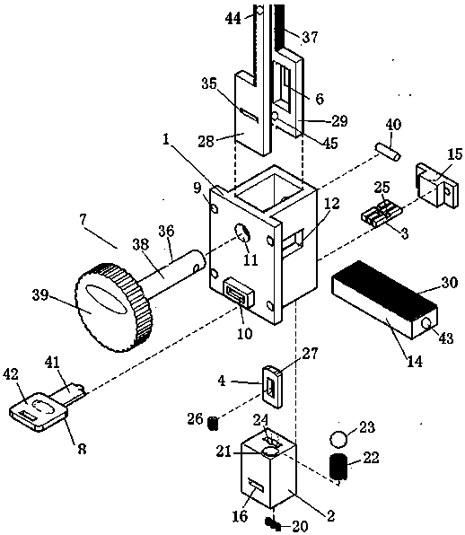
[0105] Embodiment one, with reference to the attached Figure 1-14 .

[0106] An isolated anti-theft lock structure, called a three-way output isolation lock, comprising a housing 1, a lock cylinder 2, a slider 3, a stop valve 4, a scissors body, a key 8 and a rotating rod 38; There is a keyhole 10, and the housing 1 is provided with a lock core 2 and a scissors body; the lock core 2 is provided with a rectangular hole 16 from the front face to the rear face, and the front section of the rectangular hole 16 matches the key hole 10, and the rectangular hole 16 is rectangular. The back section of the hole 16 forms 3 or 4 slider holes 18 through the grid, and a slider 3 is provided in the slider hole 18, and a slider groove 25 is provided on the slider 3; the stop valve 4 is arranged on the lock cylinder 2, the top of the stop valve 4 exposes the upper surface of the lock cylinder 2, and the bottom of the stop valve 4 is in contact with the slider 3; The upper surface of 14 is ...

Embodiment 2

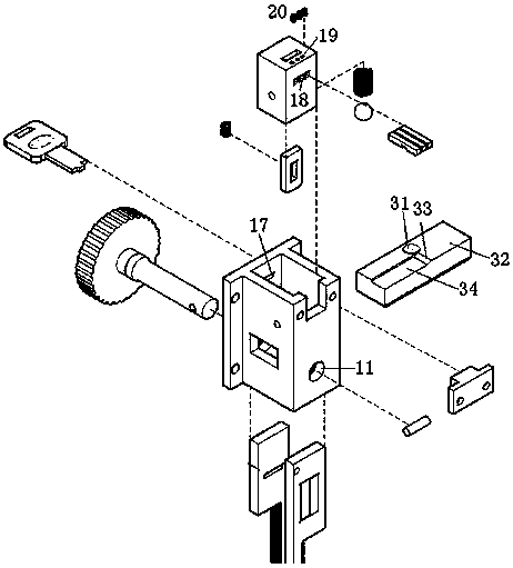
[0123] Embodiment two, referring to the attached Figure 15-23 .

[0124] An isolated anti-theft lock structure, called a rotary isolation lock, includes a housing 1, a lock cylinder 2, a slider 3, a stop valve 4, a scissor body 5, a slider return device, a key and a rotating rod 38; The housing 1 is provided with a lock cylinder 2, a stop valve 4 and a scissors body 5. The inner surface of the housing 1 is provided with a double-slope groove 33, and the double-slope groove 33 extends from the front end surface of the housing 1 to the rear end surface. There is a rear end cover 15; the rotating rod 38 and the lock cylinder 2 are in an integrated stepped shaft structure, and one end of the rotating rod 38 is provided with a key hole, which is located at the front end of the housing 1, and the other end of the rotating rod 38 is provided with a dead bolt 49, and the lock The tongue 49 passes through the rear end cover 15 of the shell 1, and the rotating rod 38 is provided with ...

Embodiment 3

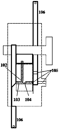
[0141] Embodiment three, with reference to the attached Figure 24-30 .

[0142]An isolated anti-theft lock structure, called an additional isolated lock, comprising a housing 1, a lock cylinder 2, a slider 3, a supporting member 51 and a key; a button 56 is provided on the front end of the housing 1, and a There is a keyhole 10, a rear end cover 15 is fixed on the rear end surface, and a cylinder 47 is arranged on the inner side of the rear end cover 15; the supporting member 51 is arranged in the casing 1, and the supporting member 51 is slidably connected with the casing 1 in the horizontal direction. A return spring 57 is provided between the supporting member 51 and the rear end cover 15; the lock core 2 and the supporting member 51 are vertically slidably connected through the vertical rib 55 on the supporting member 51, and the lock core 2 is provided with Rectangular hole 16, and rectangular hole 16 cooperates with key hole 10, constitutes variable key channel, and re...


PUM


Abstract

The invention relates to an isolated anti-theft lock structure and belongs to the technical field of hardware locks. A casing is a hollow cuboid or a cylinder used for containing and assembling all parts. A user can detach a rear end cover and replace a slider by himself or herself to conduct encryption. A movable slide for a lock cylinder, a scissors body or a check valve is arranged on the inner surface. The slider is an I-shaped or U-shaped cuboid strip installed in the lock cylinder, and a slider slot for the check valve to fall in or pass is formed in the slider. When a location ball or double inclines of a key hole through location device enter the location hole or double slots, a key can be inserted to push the slider to move. The isolated anti-theft lock structure has the three-direction output type, the rotating type, the addition type, the key-free type, the movable type and the cluster typical type. Unlocking can be conducted only after the key is pulled out, the qualitative leap of the anti-theft technology from increasing the stealing unlocking difficulty to completely eradicating stealing unlocking is achieved. Meanwhile, the original lock is not required to be disassembled, a layer of anti-theft protection is added on the isolation lock, and users with the anti-theft lock can use the structure conveniently.

Description

technical field [0001] The invention relates to an isolated anti-theft lock structure, which belongs to the technical field of hardware locks. Background technique [0002] Anti-theft locks are inseparable from everyone and are an important device that is used almost every day. Based on reasons such as practicality, cheapness, convenience, and durability, mechanical anti-theft locks occupy an absolute market all the time. Although it has been improved from generation to generation, one technology after another, its security is still very fragile. The most common tumbler lock is taken as an example below to illustrate the major problems in the prior art, and analyze the reasons why the problem has not been completely cured. [0003] The pin lock is to use the length or uneven shape of the key to squeeze the pins in the lock cylinder to make them all reach the appropriate position, and unlock the lock without preventing the rotation of the lock cylinder. After the key is pu...

Claims


Application Information

Patent Timeline
Patent Type & Authority Patents(China)
IPC IPC(8): E05B27/00E05B67/00E05B63/14E05B19/00
Inventor 孟德玉
Owner 孟德玉
Why Eureka
Try Eureka