Engine oil inlet pipe joint and machining method thereof

A processing method and oil inlet pipe technology, which is applied in the direction of engine components, machines/engines, mechanical equipment, etc., can solve the problems of rubber hose 02 falling off, increasing the processing allowance of fastening nut 01, and weak connection, etc., so as to reduce the cutting residue Quantity, improve reliability and firmness, and reduce production cost

Inactive Publication Date: 2015-04-29
NINGBO T ERRE AUTOMOTIVE COMPONENTS
View PDF5 Cites 4 Cited by
  • Summary
  • Abstract
  • Description
  • Claims
  • Application Information

AI Technical Summary

Problems solved by technology

[0007] The above processing method has the following disadvantages: the fastening nut 01 and the sleeve 03 are integrally formed, and the fastening nut 01 needs to fit on the outer wall of the bamboo-shaped connecting pipe 04, so the inner hole of the fastening nut 01 needs to be cut processing, and then increased the machining allowance of the fastening nut 01; in addition, the rubber hose 02 is fixed at the joint of the engine oil inlet pipe through the annular protrusion on the outer wall of the bamboo joint pipe 04 and the inner wall of the casing 03, but the rubber hose 02 only has The inner wall is limited, so it is easy to cause the connection to be weak, that is, the rubber hose 02 is very easy to fall off from the engine oil inlet pipe joint

Method used


Image

  • Engine oil inlet pipe joint and machining method thereof
  • Engine oil inlet pipe joint and machining method thereof

Examples


specific Embodiment approach

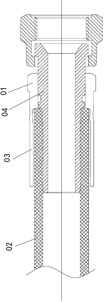
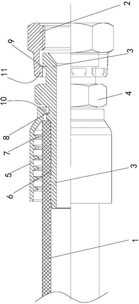
[0027] An engine oil inlet pipe joint, which is connected with a rubber hose 1, a bamboo joint pipe 3, a casing 5, a fastening nut 2 and an external nut, and the fastening nut 4 is integrally formed with the bamboo joint pipe 3; The nut 2 fits on one end of the bamboo joint pipe 3, the sleeve 5 fits outside the other end of the bamboo joint pipe 3; the rubber hose 1 is located between the outer wall of the bamboo joint pipe 3 and the inner wall of the sleeve 5, and the bamboo joint The outer wall of the connecting pipe 3 is provided with a plurality of annular protrusions 6 embedded in the inner wall of the rubber hose 1 , and the inner wall of the sleeve 5 is provided with a plurality of locking teeth 7 embedded in the outer wall of the rubber hose 1 .

[0028] The outer wall of the bamboo joint pipe 3 is provided with a first annular groove 8 and a second annular groove 9, one end of the sleeve 5 is provided with a first protruding ring 10 embedded in the first annular groove...


PUM


Abstract

The invention discloses an engine oil inlet pipe joint and a machining method thereof. The engine oil inlet pipe joint comprises a bamboo joint type connecting pipe (3), a bushing (5), a fastening nut (4) and an external nut (2), wherein the bamboo joint type connecting pipe (3) is connected with a rubber pipe (1); the fastening nut (4) and the bamboo joint type connecting pipe (3) are integrally formed; the external nut (2) sleeves one end of the bamboo joint type connecting pipe (3); the bushing (5) sleeves the outer side of the other end of the bamboo joint type connecting pipe (3); the rubber pipe (1) is positioned between the outer wall of the bamboo joint type connecting pipe (3) and the inner wall of the bushing (5); the outer wall of the bamboo joint type connecting pipe (3) is provided with a plurality of annular bumps (6) which are embedded into the inner wall of the rubber pipe (1); the inner wall of the bushing (5) is provided with a plurality of clamping teeth (7) which are embedded into the outer wall of the rubber pipe (1). The engine oil inlet pipe joint which is low in production cost and reliable in rubber pipe connection and the engine oil inlet pipe joint machining method which is simple in machining processes and firm and reliable in rubber pipe connection are provided.

Description

technical field [0001] The invention relates to the technical field of an engine oil inlet pipe joint, in particular to an engine oil inlet pipe joint and a processing method thereof. Background technique [0002] The existing engine oil inlet pipe joint is a connecting piece used for oil delivery pipes. In order to ensure the normal operation of the engine, there are high requirements on the reliability and sealing performance of the connection of the oil inlet pipe joint. At present, the structure of the engine oil inlet pipe joint, such as figure 1 As shown, it includes fastening nut 01, rubber hose 02, sleeve 03 and bamboo joint pipe 04. The fastening nut 01 and the sleeve 03 are integrally formed. The outer wall of the jointed connecting pipe 04, the end of the rubber hose 01 is located between the inner wall of the casing 03 and the outer wall of the bamboo jointed connecting pipe 04. [0003] The engine oil inlet pipe joint of this structure is because the casing 03...

Claims


Application Information

Patent Timeline
Patent Type & Authority Applications(China)
IPC IPC(8): F02M37/00B23P15/00
Inventor 董阿能白永洁陈荣发
Owner NINGBO T ERRE AUTOMOTIVE COMPONENTS
Why Eureka
Try Eureka