Brake disc

A disc and brake technology, which is applied in the field of floating brake discs, can solve the problems of affecting structural strength and safety in use, weak structural strength, and wear of the outer edge of the depression.

Inactive Publication Date: 2015-04-29
温芫鋐
View PDF9 Cites 4 Cited by
  • Summary
  • Abstract
  • Description
  • Claims
  • Application Information

AI Technical Summary

Problems solved by technology

[0002] Known brake discs are mostly single-piece, the outer ring is clamped by the caliper for braking action, and the central part is used to connect with the hub to move together. However, the high heat generated by the brake in this structure will be transmitted to the hub through the disc and produce adverse effects
[0003] Therefore, there has been a two-piece combined brake disc, which is composed of an inner disc connected to the flower hub and an outer disc clamped by the caliper. The outer disc center has a hole for the inner disc to be set. The parts are fixed, so as to reduce the high heat conduction generated by the brakes to the hub. Among them, there is a kind of outer disc and inner disc that partially overlap each other and pass through the outer disc and the inner disc at the same time with positioning parts, such as Chinese Taiwan patents 451855, I318188, M473983, M473984, etc. As mentioned above, this kind of structure must perforate the outer plate and the inner plate separately, and the contact area between the outer plate and the inner plate is still quite large, and the heat insulation effect is not good. In addition, the inner and outer plates are fixed to each other only by the positioning parts, and the structural strength is relatively weak
[0004] In addition, there is another kind of floating disc, as disclosed in Chinese Taiwan patents 335113, I404643, M243588, M271985, M306566, M386212, M409216, M451445, etc., which also have inner and outer discs, but the combination is in the inner disc. 1. The outer disk is respectively provided with a depression or a U-shaped part, and the two depressions are opposite to each other to enclose a perforation, and then the positioning piece is passed through the perforation to fix it. Although this type of structure has better advantages than the structure described in the previous paragraph However, since the positioning piece is sandwiched between the inner and outer plates, the heat may still be transferred to the inner plate through the positioning piece. In addition, in order to avoid the relative rotation of the inner and outer plates, the depression or U-shaped part must be specially designed to engage with each other. Any dimensional error may make it unusable, and after long-term use, the outer edge of the depression may be severely worn, affecting the structural strength and safety of use

Method used


Image

  • Brake disc
  • Brake disc
  • Brake disc

Examples


Embodiment Construction

[0023] The following examples illustrate possible implementations of the present invention, but they are not intended to limit the protection scope of the present invention and are described in advance.

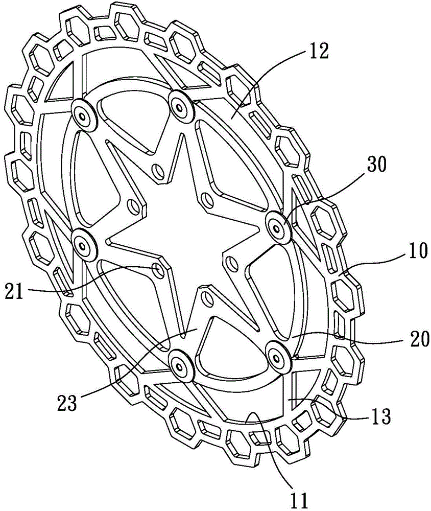
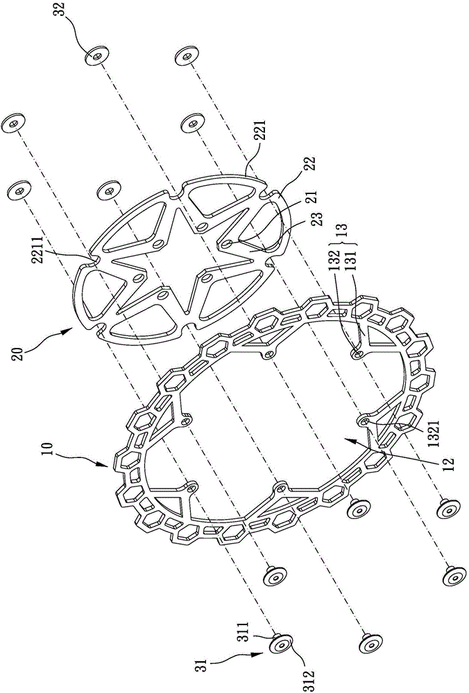
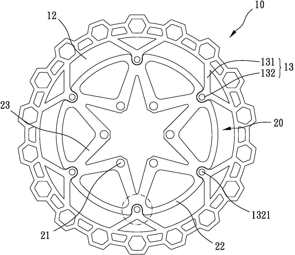
[0024] Please refer to figure 1 Referring to FIG. 5 , the present invention provides a brake disc, including an outer disc 10 , an inner disc 20 and a plurality of positioning elements 30 .

[0025] The outer disc 10 is generally ring-shaped and forms a perforation 12 in its center. The perforation 12 defines a central axis, and the central axis defines an axial direction. The outer disc 10 has an inner rim 11 surrounding the inner rim 11. The through hole 12 is formed, the inner ring edge 11 of the outer disk 10 is formed with a plurality of connecting bridges 13 arranged at intervals, and each connecting bridge 13 is formed to extend radially toward the central axis of the through hole 12, and the connecting bridges 13 are farther away from the outer disk. One end of the i...


PUM


Abstract

The invention provides a brake disc. The brake disc comprises an outer disc, an inner disc and a plurality of positioning parts, wherein the outer disc is annular, and is defined with an axial direction; a plurality of connection bridges which are arranged at intervals and extend towards a middle axle are formed on the inner ring edge of the outer disc; the free ends of the connection bridges are provided convex parts; through holes are formed in the convex parts in the axial directions; the inner disc is coaxially arranged in the center of the outer disc and is positioned on the same plane with the outer disc; a plurality of concave parts which are arranged at intervals are arranged in the outer ring edge of the inner disc; the plurality of concave parts correspond to the plurality of convex parts respectively; the convex parts are just embedded into the concave parts to avoid rotation of the inner disc relative to the outer disc; a gap is formed between each concave parts and each convex part; each positioning part passes through the corresponding through hole to limit relative movement of the outer disc and the inner disc along the axial direction; the outer disc and the inner disc are not overlapped in the axial direction at all. The brake disc is a floating brake disc which has a good heat-insulating effect and high structural strength.

Description

technical field [0001] The invention relates to a brake disc, in particular to a floating brake disc. Background technique [0002] Known brake discs are mostly single-piece, the outer ring is clamped by the caliper for braking action, and the central part is used to connect with the hub to move together. However, the high heat generated by the brake in this structure will be transmitted to the hub through the disc produce adverse effects. [0003] Therefore, there has been a two-piece combined brake disc, which is composed of an inner disc connected to the flower hub and an outer disc clamped by the caliper. The outer disc center has a hole for the inner disc to be set. The parts are fixed, so as to reduce the high heat conduction generated by the brakes to the hub. Among them, there is a kind of outer disc and inner disc that partially overlap each other and pass through the outer disc and the inner disc at the same time with positioning parts, such as Chinese Taiwan pate...

Claims


Application Information

Patent Timeline
Patent Type & Authority Applications(China)
IPC IPC(8): F16D65/12F16D65/847
Inventor 温芫鋐
Owner 温芫鋐
Why Eureka
Try Eureka