

Microwave oven door handle
A technology for microwave ovens and door handles, applied in the field of microwave ovens, can solve problems such as burns, and achieve the effect of expanding the contact area
- Summary
- Abstract
- Description
- Claims
- Application Information
AI Technical Summary
Problems solved by technology
Method used
Image

Examples
Embodiment Construction
[0020] Below in conjunction with accompanying drawing and specific embodiment the present invention is described in further detail:
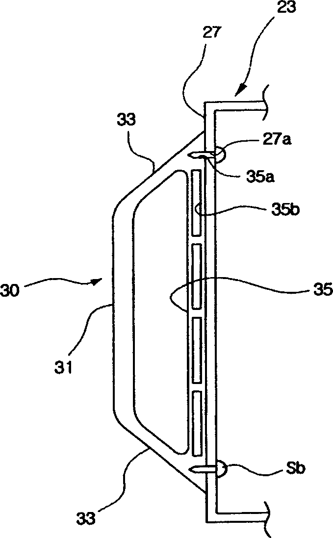
[0021] Such as image 3 As shown, the front appearance of the microwave oven door 23 is formed by the oven door panel 27 . The oven door panel 27 may be fabricated from metal. A pair of assembling holes 27a are formed in the upper and lower parts of one side of the front surface of the oven door panel 27 . A door handle 30 is mounted on one side of the oven door panel 27 .
[0022] The door handle 30 is used to turn the furnace door 23, including a handle part 31 for the user to grasp; a contact part 35 closely contacted with the furnace door panel 27; a connecting part 33 connecting the handle part 31 and the contact part 35; On the cooling hole 35b.
[0023] The handle portion 31 has a rod shape and is arranged vertically. Connecting parts 33 are respectively connected to upper and lower ends of the handle part 31 . Each connecting porti...
PUM
 Abstract
Description
Claims
Application Information