Clamp connection type lamp head

A clip-on, lamp holder technology, applied in the direction of lighting devices, cooling/heating devices of lighting devices, components of lighting devices, etc., can solve the problem that the total length of the cylindrical area is difficult to adjust, the angle of inclination is difficult to adjust, and the length of the lamp head can be adjusted, etc. question

Inactive Publication Date: 2015-04-29
SUZHOU KUNK & SAM LIGHTING TECH CO LTD
View PDF7 Cites 0 Cited by
  • Summary
  • Abstract
  • Description
  • Claims
  • Application Information

AI Technical Summary

Problems solved by technology

[0002] The existing vehicle lamp cap and the lamp holder are integrally fixedly connected, and the lamp cap is installed obliquely relative to the lamp holder, but because of the fixed connection, the inclination angle is difficult to adjust
At the same

Method used


Image

  • Clamp connection type lamp head

Examples


Embodiment Construction

[0014] In order to make the technical solutions, technical features, goals and effects achieved by the present invention easy to understand, the present invention will be further elaborated below in conjunction with specific embodiments and accompanying drawings.

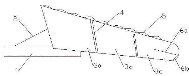
[0015] according to figure 1 , a clip-on lamp cap, including a lamp holder 1, characterized in that it includes a lamp head connected to the lamp holder 1 through an inclined connecting bolt 2, and the diameter of the lamp head is divided into first The lamp head 3a, the second lamp head 3b, and the third lamp head 3c, between the first lamp head and the second lamp head, between the second lamp head and the third lamp head, respectively A first rotating member and a second rotating member (collectively referred to as rotating member 4) are provided.

[0016] The end of the third lamp head is connected to a detachable elastic abutting part, one end of the elastic abutting part is connected to the end of the third l...


PUM


Abstract

The invention relates to the field of lamps, in particular to a clamp connection type lamp head. The clamp connection type lamp head comprises a lamp holder, and is characterized by comprising a lamp head part connected with the lamp holder through an inclined connecting bolt, wherein the lamp head part is divided into a first lamp head part, a second lamp head part and a third lamp head part from large-diameter to small-diameter, and a first rotating component and a second rotating component are respectively arranged between the first lamp head part and the second lamp head part and between the second lamp head part and the third lamp head part. According to the clamp connection type lamp head, a spiral copper tube is used for heat radiation, and the third lamp head part is embedded into the second lamp head part and can be continuously and inwards embedded (i.e., the embedding depth is increased) or can be outwards pushed out (i.e., the embedding depth is reduced), and an elastic abutting component is abutted against the second rotating component and the tail end of the third lamp head part for achieving the positioning effect on the second rotating component and the third lamp head part, and the unnecessary embedding into a deeper position or to a shallower position can be prevented; when the positioning is not needed, the elastic abutting part is abutted against the radial outer surface of the third lamp head part. The rotating components can enable different lamp head parts to rotate.

Description

technical field [0001] The invention relates to the field of lamps, in particular to a clip-on lamp holder. Background technique [0002] The existing vehicle lamp cap is integrally fixedly connected with the lamp holder, and the lamp cap is arranged obliquely relative to the lamp holder, but because of the fixed connection, it is difficult to adjust the inclination angle. At the same time, the lamp cap is composed of several cylindrical regions with different diameters, but the total length of the cylindrical regions is difficult to adjust, and it is difficult to adjust the length of the lamp cap according to the size of different vehicles. Contents of the invention [0003] The technical purpose of the present invention is to overcome the problems in the prior art, and provide a clip-on lamp holder with good heat dissipation, length conversion, rotation and fixation. [0004] In order to achieve the purpose of the present invention, the technical solution adopted in...

Claims


Application Information

Patent Timeline
IPC IPC(8): F21V21/00F21V29/89
CPCF21V19/006F21V21/116
Inventor 傅立铭
Owner SUZHOU KUNK & SAM LIGHTING TECH CO LTD
Why Eureka
Try Eureka