Optical lens, camera module and assembly method thereof

An optical lens and lens technology, which is applied in the field of optical imaging, can solve the problems of image quality degradation and product failure, and achieve the effects of reducing deformation, reducing lens position offset, and increasing bonding area

Active Publication Date: 2022-07-26
NINGBO SUNNY OPOTECH CO LTD
View PDF31 Cites 0 Cited by
  • Summary
  • Abstract
  • Description
  • Claims
  • Application Information

AI Technical Summary

Problems solved by technology

However, the actual trial production found that the imaging quality of the optical lens and camera module often deteriorates compared with the imaging quality obtained in the active calibration stage. This degradation sometimes exceeds the tolerance range, resulting in defective products
The applicant's research found that after the active calibration process was introduced into the assembly of the optical lens or camera module, the variation of the glue material, lens barrel or lens, and other unknown factors may be the cause of the above problems

Method used


Image

  • Optical lens, camera module and assembly method thereof
  • Optical lens, camera module and assembly method thereof
  • Optical lens, camera module and assembly method thereof

Examples


Embodiment Construction

[0155] For a better understanding of the present application, various aspects of the present application will be described in more detail with reference to the accompanying drawings. It should be understood that these detailed descriptions are merely illustrative of exemplary embodiments of the present application and are not intended to limit the scope of the present application in any way. Throughout the specification, the same reference numerals refer to the same elements. The expression "and / or" includes any and all combinations of one or more of the associated listed items.

[0156] It should be noted that in this specification, the expressions first, second, etc. are only used to distinguish one feature from another feature and do not imply any limitation on the feature. Accordingly, the first body discussed below could also be referred to as a second body without departing from the teachings of the present application.

[0157] In the drawings, the thickness, size and...


PUM


Abstract

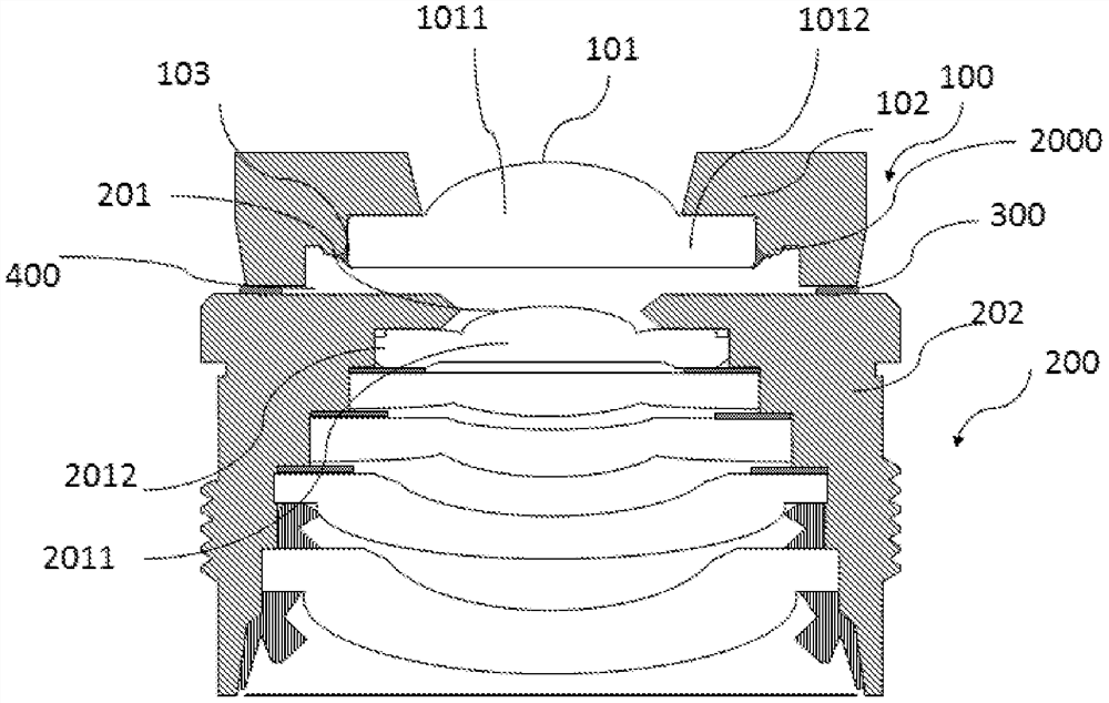
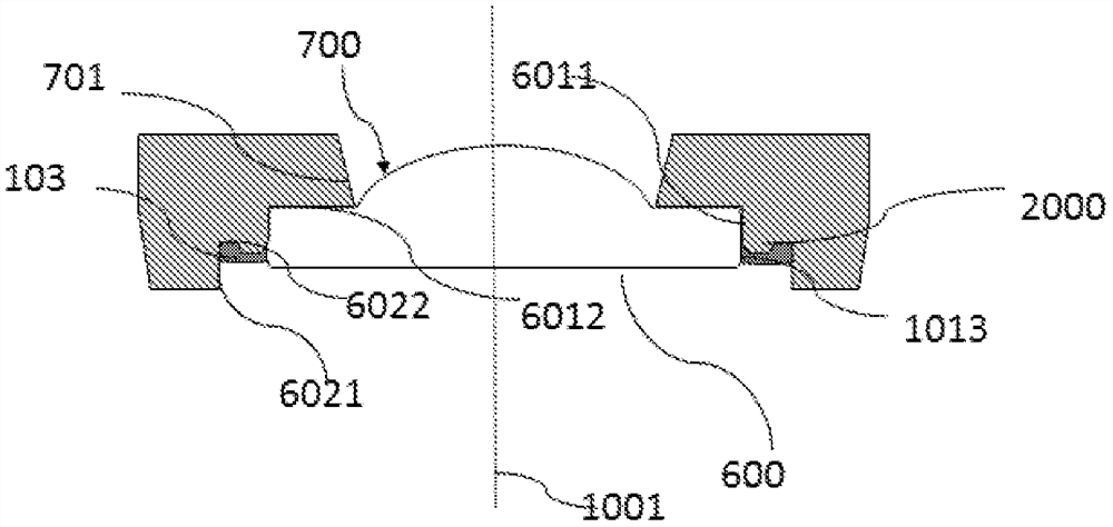
An optical lens includes a first lens component (100). The first lens component (100) includes one or more first lenses (101), a first lens barrel (102) and an adhesive (103). The inner side of the first lens barrel (102) is provided with a composite accommodating hole (600), at least one first lens (101) is embedded in the composite accommodating hole (600), and the composite accommodating hole (600) includes an annular accommodating area side wall ( 6011). The outer side of the embedded first lens (101) includes a first area (10131) and a second area (10132), and the first area (10131) and the second area (10132) are staggered. The first area (10131) is the area of ​​the outer side of the first lens (101) that is supported against the side wall (6011) of the accommodating area, and the second area (10132) is the area of ​​the outer side of the first lens (101) exposed on the side wall (6011). The area outside the side wall (6011) of the accommodating area. The adhesive glue (103) adheres the first lens barrel (102) to the first lens (101) by contacting the second area (10132). The optical lens, the corresponding camera module, and the assembling method of the optical lens and the camera module can reduce the lens position shift caused by the deformation of the lens barrel, and can improve the imaging quality of the optical lens or the camera module.

Description

[0001] cross reference [0002] This application requires the invention patent application No. 201810584364.7, which was submitted to the China Patent Office on June 8, 2018, and the invention name is "optical lens, camera module and its assembly method", and was submitted to the China Patent Office on June 8, 2018. The priority of the utility model patent application No. 201820882490.6, named "optical lens, camera module", submitted to the Chinese Patent Office on May 30, 2018, and the invention name is "optical lens, camera module and its assembly" Method" for invention patent application No. 201810541239.8, and the priority of utility model patent application No. 201820822167.X titled "optical lens and camera module" filed with the China Patent Office on May 30, 2018, the above patent application The entire contents of are incorporated herein by reference. technical field [0003] The present application relates to the technical field of optical imaging, and in particular,...

Claims


Application Information

Patent Timeline
Patent Type & Authority Patents(China)
IPC IPC(8): G02B7/02
Inventor 陈烈烽田中武彦梅其敏蒋恒
Owner NINGBO SUNNY OPOTECH CO LTD
Why Eureka
Try Eureka