Lens, lens assembly and manufacture method of lens

A manufacturing method and lens technology, applied in the directions of lens, installation, optics, etc., can solve the problems of difficulty in gasket manufacturing, limitation of gasket arrangement, inability to arrange gaskets, etc., and achieve the effect of improving efficiency, reducing quantity, and improving the quality of imaging

Inactive Publication Date: 2015-04-29
GENIUS ELECTRONICS OPTICAL XIAMEN
View PDF6 Cites 35 Cited by
  • Summary
  • Abstract
  • Description
  • Claims
  • Application Information

AI Technical Summary

Problems solved by technology

[0003] However, consumers have higher and higher requirements for image quality, coupled with the thinning trend of photographic lenses, the size of gaskets must be smaller, and the effect of eliminating stray light must be better, making the manufacture of gaskets more difficult; In addition, the gasket can only be laid flat on the surface of the lens. If the surface of the lens has a tapered surface, the gasket cannot be installed, which makes the installation of the gasket very limited. Therefore, the industry has been actively looking for other methods that can assist or even replace the traditional method of eliminating stray light.

Method used


Image

  • Lens, lens assembly and manufacture method of lens
  • Lens, lens assembly and manufacture method of lens
  • Lens, lens assembly and manufacture method of lens

Examples


Embodiment 1

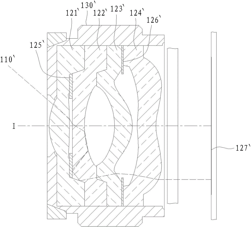
[0068] refer to Figure 2A and Figure 2B Shown, this embodiment is a kind of lens, comprises:

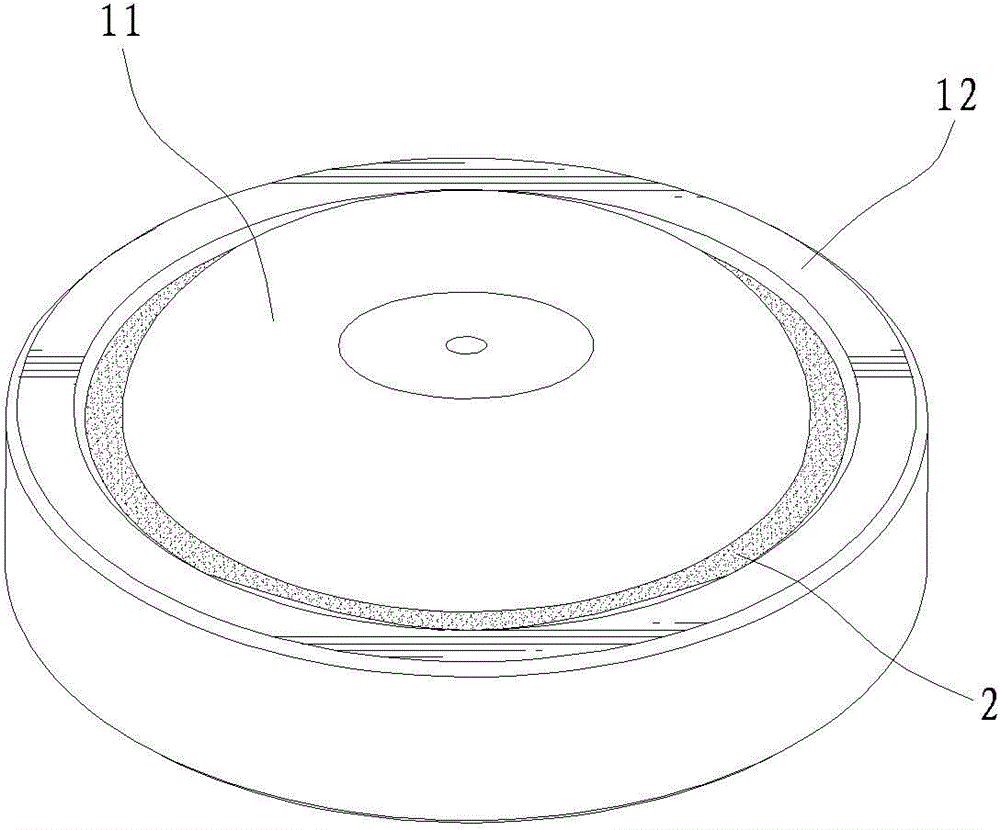
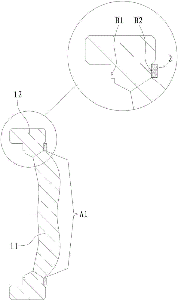
[0069] A lens body 1 includes an optically effective portion 11 and an extension portion 12. The optically effective portion 11 refers to the area A1 for the ideal imaging light to pass through. The extension portion 12 is annular and defined by the outer circumference of the optically effective diameter The edge extends to the outer peripheral edge of the lens body, and the extension portion 12 surrounds the optical effective portion 11, and the ideal imaging light does not pass through the extension portion 12, the lens body 1 has a The annular surface B1 outside A1 and the annular surface B2 facing the image side and located outside the optically effective part A1, that is, the extension part 12 corresponds to the side of the two light-transmitting surfaces (object side and image side) of the lens body Each has an annular surface B1, B2. The annular surface B2 in this embodim...

Embodiment 2

[0072] refer to image 3 As shown, this embodiment is basically the same as Embodiment 1, except that the light blocking layer 2 is formed on the annular surface B1 of the extension portion 12 in addition to being formed on the annular surface B2 of the extension portion 12 . Similarly, the material selection of the light-blocking layer 2 and the manner in which the light-blocking layer 2 is formed on the annular surfaces B1 and B2 of the extension portion 12 can refer to the description of the first embodiment.

Embodiment 3

[0074] refer to Figure 4 As shown, this embodiment is basically the same as Embodiment 1, except that: the surface of the lens body 1 includes an anti-reflection layer (anti-reflection layer) 3 covering the optical effective part 11 and the extension part 12, covering the The lens body 1 of the anti-reflection layer 3 can improve the optical transmittance. In this embodiment, after the anti-reflection layer 3 is pre-covered (usually by coating) on ​​the optically effective part 11 and the extension part 12 of the lens body 1, the light blocking layer 2 is formed on the annular surface B2 of the extension part 12. covered by an anti-reflection layer 3 outside. This method is more realized by processing.


PUM


Abstract

A lens includes: a lens body, including an optical effective part and an extending part, wherein the extending part surrounds a periphery region of the optical effective part, and the extending part has at least one annular surface; and an opaque layer, disposed on the annular surface of the extending part. An optical imaging lens set includes a barrel; and an imaging component is disposed in the barrel. The imaging component includes at least one lens arranged along an optical axis, and one of these lenses is the lens mentioned above. A method for forming a lens forms the opaque layer on the annular surface of the extending part through a stamping method or through an evaporation method.

Description

technical field [0001] The invention relates to the field of optical device manufacturing, in particular to a lens, a lens and a manufacturing method thereof. Background technique [0002] General photography lenses such as figure 1 As shown, it generally includes a lens barrel, a plurality of lenses, and several gaskets, wherein the gasket is arranged between the lens barrel and the lenses, or between the lenses, and is made of light-tight and anti-reflection Made of materials, when the light passes through the lenses and forms an image on an imaging surface, the gasket can absorb or reflect stray light to prevent the stray light from reaching the imaging surface and cause flare (flare), so as to improve the quality of imaging . [0003] However, consumers have higher and higher requirements for image quality, coupled with the thinning trend of photographic lenses, the size of gaskets must be smaller, and the effect of eliminating stray light must be better, making the ma...

Claims


Application Information

Patent Timeline
Patent Type & Authority Applications(China)
IPC IPC(8): G02B3/00G02B1/11G02B7/02
CPCG02B1/11G02B7/021
Inventor 陈申杰
Owner GENIUS ELECTRONICS OPTICAL XIAMEN
Why Eureka
Try Eureka