Color filter substrate and display device

A color filter substrate and display area technology, applied in optics, nonlinear optics, instruments, etc., can solve the problems of color shift, edge display area color shift, edge display area sawtooth phenomenon, etc., to improve continuity, improve Visual effects, the effect of avoiding color casts

Active Publication Date: 2015-04-29
SHANGHAI TIANMA MICRO ELECTRONICS CO LTD +1
View PDF3 Cites 64 Cited by
  • Summary
  • Abstract
  • Description
  • Claims
  • Application Information

AI Technical Summary

Problems solved by technology

When no sub-pixel is set in the edge display area, there are steps in the edge area of ​​the color filter substrate, resulting in discontinuity of display information, so that the image displayed by the display device to which the color filter substrate belongs has jagged edges; sub-pixels are set in the edge display area. Pixels, when the edge display area is formed by blo...

Method used


Image

  • Color filter substrate and display device
  • Color filter substrate and display device
  • Color filter substrate and display device

Examples


Embodiment 1

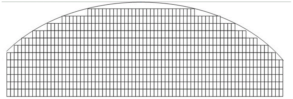
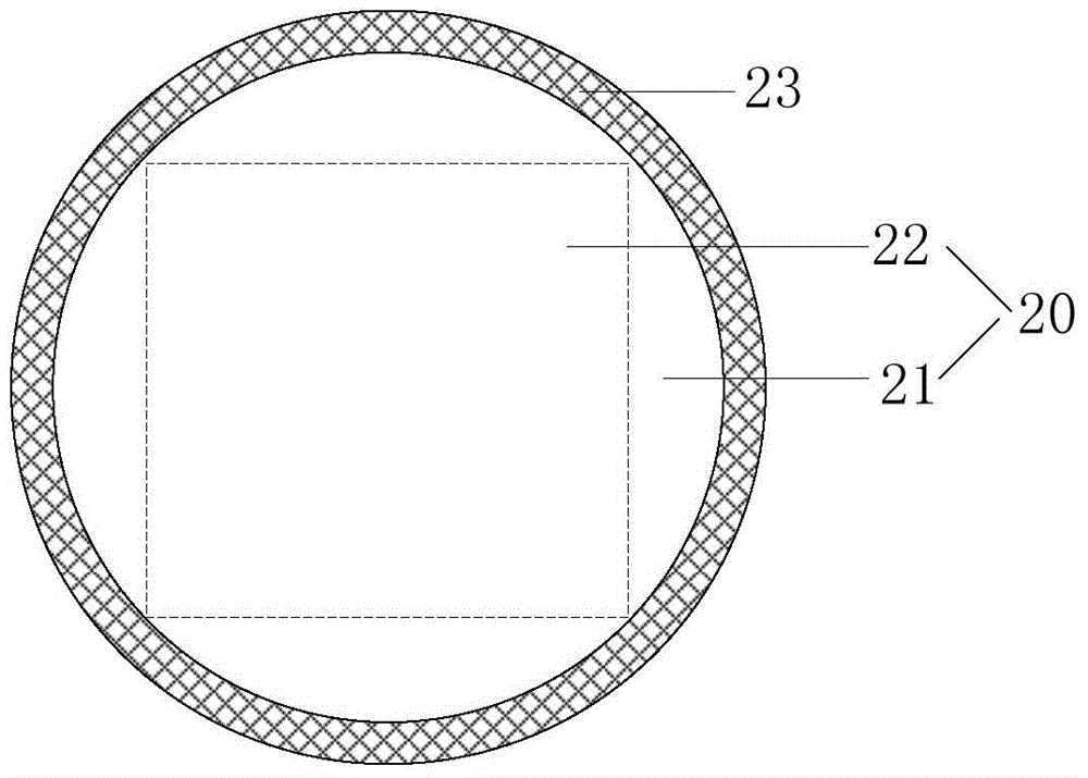
[0029] Figure 2a It is a schematic top view of a color filter substrate provided in Embodiment 1 of the present invention, Figure 2b It is a schematic plan view of the edge display area of ​​a color filter substrate provided in Embodiment 1 of the present invention, now combined with Figure 2a and Figure 2b A first embodiment of the present invention will be described. Such as Figure 2a As shown, the color filter substrate includes a non-rectangular display area 20 and a non-display area 23 arranged around the display area 20 , and the display area 20 includes an edge display area 21 close to the non-display area 23 . The shape of the edge of the display area 20 can be non-rectangular, such as parallelogram, trapezoid, ellipse or circle, etc. The shape of the edge of the display area 20 can also be a rectangle with non-linear edges, such as a Rectangles with non-straight sides such as wavy, zigzag, and broken lines, and rectangles with non-straight sides are still not...

Embodiment 2

[0039] image 3 It is a schematic top view of an edge display area provided in Embodiment 2 of the present invention. On the basis of Embodiment 1 of the present invention, Embodiment 2 of the present invention specifically defines the edge display area as follows: in the edge display area, the light transmission area corresponding to each sub-pixel in each row of sub-pixel units accounts for The area specific gravity values ​​sequentially form an arithmetic sequence along the row direction, and the tolerances of the arithmetic sequence formed by the light transmission area corresponding to each sub-pixel in each row of sub-pixel units to the sub-pixel area are the same. In addition, in this embodiment, the direction from left to right is taken as the reference direction.

[0040] It should be noted that the edge display regions provided in the various embodiments of the present invention correspond to different edge shapes of the display regions, which will not be repeated i...

Embodiment 3

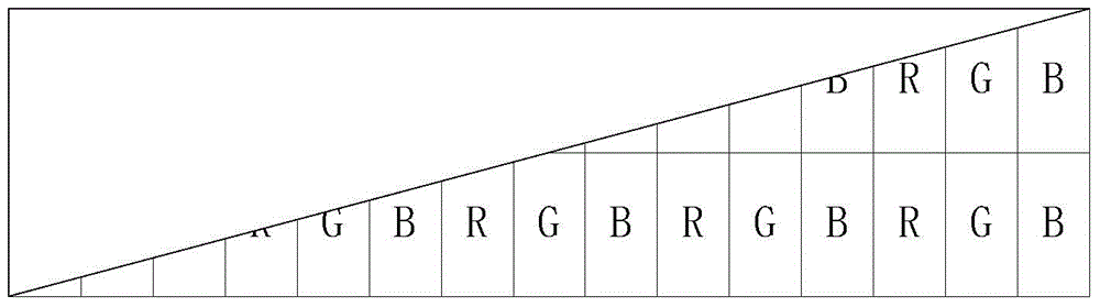
[0047] Figure 4a It is a schematic plan view of an edge display area of ​​a color filter substrate provided in Embodiment 3 of the present invention. On the basis of the above-mentioned embodiments, Embodiment 3 of the present invention specifically defines the edge display area as follows: the edge display area includes a plurality of pixel units, and each pixel unit includes a first sub-pixel, a second sub-pixel and A third sub-pixel, the sorting of various sub-pixels in the pixel unit changes according to preset rules. In this embodiment, the edge display area is introduced by taking the first sub-pixel as R, the second sub-pixel as G and the third sub-pixel as B as an example. In addition, in this embodiment, the direction from left to right is taken as the reference direction.

[0048] Such as Figure 4a As shown, the edge display area includes two adjacent pixel units, wherein the second sub-pixel G, the third sub-pixel B and the first sub-pixel R in one pixel unit a...


PUM


Abstract

The invention relates to the technical field of display, in particular to a color filter substrate and a display device. The color filter substrate comprises a non-rectangular display area and a non-display area surrounding the display area; the display area comprises an edge display area near the non-display area; the edge display area comprises a black matrix and a plurality of first sub-pixels, a plurality of second sub-pixels and a plurality of third sub-pixels, wherein the first sub-pixels, the second sub-pixels and the third sub-pixels are defined by the black matrix; the total that light transmission area corresponding to the first sub-pixels accounts for the area proportion value of the sub-pixels is P1; the total that light transmission area corresponding to the second sub-pixels accounts for the area proportion value of the sub-pixels is P2; the total that light transmission area corresponding to the third sub-pixels accounts for the area proportion value of the sub-pixels is P3; the difference value between the maximum value and the minimum value of P1, P2 and P3 is 0.3 time less than the average value of P1, P2 and P3; P1, P2 and P3 are all positive numbers greater than 0. According to the color filter substrate, the continuity of display information is increased; moreover, the proportions of the various sub-pixels blocked are approximately equal, and the visual effect of the display device is enhanced.

Description

technical field [0001] The invention relates to the field of display technology, in particular to a color filter substrate and a display device including the color filter substrate. Background technique [0002] With the rapid development of smart terminals such as smart bracelets and smart watches, the shapes of display devices in smart terminals are becoming more and more abundant, and display devices with curved borders have become very common. [0003] Figure 1a and Figure 1b Both are structural schematic diagrams of color filter substrates of existing display devices. combine Figure 1a-Figure 1b As shown, when the color filter substrate has an arc-shaped boundary, the area of ​​the edge display area near the arc-shaped boundary is small, which is not enough to set a complete pixel. When no sub-pixel is set in the edge display area, there are steps in the edge area of ​​the color filter substrate, resulting in discontinuity of display information, so that the image...

Claims


Application Information

Patent Timeline
IPC IPC(8): G02F1/1335
CPCG02F1/133514G02F2201/52G02F2201/56G02F1/133512
Inventor 袁永王超
Owner SHANGHAI TIANMA MICRO ELECTRONICS CO LTD
Why Eureka
Try Eureka