Direct memory access controller, control method thereof, and information processing system
A memory and controller technology, applied in the direction of electrical digital data processing, instruments, energy-saving computing, etc., can solve problems such as packet discarding and packet loss
- Summary
- Abstract
- Description
- Claims
- Application Information
AI Technical Summary
Problems solved by technology
Method used
Image

Examples
no. 1 approach
[0041] The first embodiment will be described.
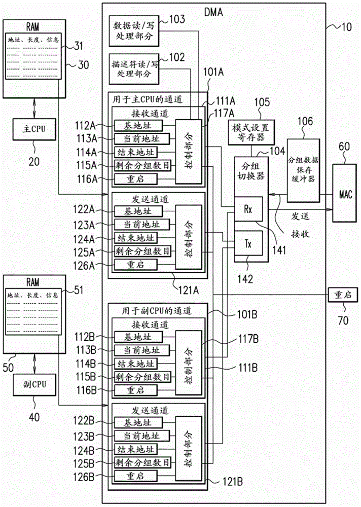
[0042] figure 1 is a diagram showing a configuration example of an information processing system including a direct memory access (DMA) controller according to the first embodiment. like figure 1 As shown, the information processing system includes a DMA controller 10, a main CPU (Central Processing Unit) 20, a RAM (Random Access Memory) 30 for the main CPU, a sub CPU 40, a RAM 50 for the sub CPU, and a medium access Control (MAC) section 60 .
[0043] exist figure 1 In the information processing system shown, the power consumption of the combination of the sub CPU 40 and the RAM 50 is lower than that of the combination of the main CPU 20 and the RAM 30 . In a normal operating state (normal mode), both the main CPU 20 and the sub CPU 40 are activated. On the other hand, in the standby state (standby mode), the power to the main CPU 20 and RAM 30 as a normal system is cut off so that the main CPU 20 and RAM 30 are stopped...
no. 2 approach
[0070] Next, a second embodiment is described.
[0071] In the first embodiment described above, at the time of transition from the normal mode to the standby mode, notification of power off permission from the sub CPU 40 is received, and power to the main CPU 20 and RAM 30 for the main CPU is cut off. At this time, there is a possibility that data that has not been transmitted remains in the transmission channel 121A of the main CPU channel 101A at the DMA controller 10 . The descriptor type DMA controller continues to operate until the descriptor becomes empty, and therefore, data that has not been transmitted remains in the transmission channel 121A of the main CPU channel 101A after the power to the main CPU 20 and RAM 30 is cut off. , access to the RAM 30 is performed, and a bus access error occurs.
[0072] In order to avoid the occurrence of a bus access error, it is conceivable that the sub CPU 40 resets the transmission channel 121A by using the restart processing se...
no. 3 approach
[0084] Next, a third embodiment is described.
[0085] In the above-described embodiment, at the time of transition from the normal mode to the standby mode, on the sub CPU side, from the time when the instruction indicates that the mode switching from the standby mode to the normal mode is necessary to when the activation of the main CPU, the DMA controller 10 A packet from the network is received at the time when activation of the master DMA and channel switching to the master CPU channel 101A is completed. This received packet needs to be transferred to the main CPU side, and it is conceivable to perform the transfer by inter-CPU communication, however, if inter-CPU communication is performed, control becomes complicated. Furthermore, it takes time to transfer packet data from the sub CPU side to the main CPU side by inter-CPU communication, and therefore, deterioration of packet response delay and occurrence of packet loss are incurred during this period, and there is a po...
PUM
 Abstract
Description
Claims
Application Information
PatSnap Eureka turns technology decisions into work you can execute. Powered by our Innovation Knowledge Graph, it runs expert workflows across engineering, life sciences, materials and intellectual property. Get your review-ready output in minutes.


