Battery pile mounting structure

A technology for installing structures and battery stacks, which is applied to structural parts, battery pack components, circuits, etc., and can solve problems such as low work efficiency, heavy battery stack weight, and laborious manpower hoisting.

Active Publication Date: 2015-04-29
SHENZHEN CLOU ELECTRONICS
View PDF3 Cites 4 Cited by
  • Summary
  • Abstract
  • Description
  • Claims
  • Application Information

AI Technical Summary

Problems solved by technology

Due to the heavy weight of the battery stack, manual...

Method used


Image

  • Battery pile mounting structure
  • Battery pile mounting structure
  • Battery pile mounting structure

Examples


Embodiment Construction

[0025] In order to facilitate the understanding of the present invention, the present invention will be described more fully below with reference to the associated drawings. Preferred embodiments of the invention are shown in the accompanying drawings. However, the present invention can be embodied in many different forms and is not limited to the embodiments described herein. On the contrary, the purpose of providing these embodiments is to make the disclosure of the present invention more thorough and comprehensive.

[0026] It should be noted that when an element is referred to as being “fixed” to another element, it can be directly on the other element or there can also be an intervening element. When an element is referred to as being "connected to" another element, it can be directly connected to the other element or intervening elements may also be present. The terms "vertical," "horizontal," "left," "right," and similar expressions are used herein for purposes of ill...


PUM


Abstract

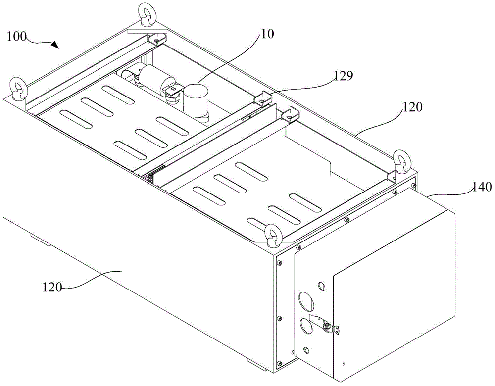
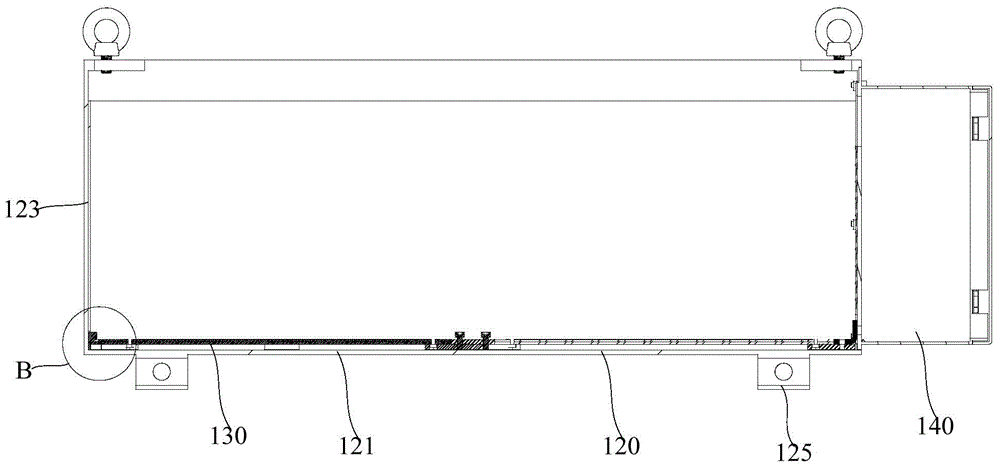
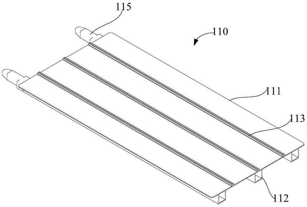
The invention relates to a battery pile mounting structure, which comprises a battery box, a pallet and a control box, wherein the pallet is used for bearing the battery pile, and the control box is used for being electrically connected with the battery pile. The battery box consists of a bottom surface and a side wall, an opening is formed in the side wall, the control box is arranged in the opening, the bottom surface, the side wall and the control box define a box body, the pallet enters the box body from the opening, and the control box and the battery box are detachably connected. A guiderail is arranged on the bottom surface of the battery box and extends towards the opening, a guide channel matched with the guiderail is formed in the side surface, towards the bottom surface, of the pallet, the guiderail enters from one end of the guide channel, the pallet slides along the guiderail and drives the battery to enter the box body. According to the battery pile mounting structure, the battery pile assembly can slide inside the battery box from the opening of the battery box. Then, the control box is arranged in the opening, so that the battery pile is contained in the battery box so as to position the battery pile assembly. The battery pile assembly is prevented from being manually hoisted into the battery box from the upside of the battery box, and the operation is convenient, and the accurate positioning of the battery pile assembly in the battery box can be guaranteed.

Description

technical field [0001] The invention relates to a mounting structure, in particular to a battery stack mounting structure. Background technique [0002] During the installation process of the battery stack, after the series and parallel connection of the battery stack is completed, the battery stack is fixedly installed on the battery stack tray to form a battery stack assembly. The operator lifts the battery stack assembly into the battery box to ensure the safety of the battery stack assembly installation. The traditional battery box only has an opening on the top surface, and the battery stack assembly needs to be hoisted and moved to the upper opening of the battery box, and then the battery stack assembly is lowered and loaded into the battery box. Due to the heavy weight of the battery stack, manual hoisting is quite laborious and the work efficiency is low. Contents of the invention [0003] Based on this, it is necessary to provide a battery stack installation st...

Claims


Application Information

Patent Timeline
IPC IPC(8): H01M2/10H01M50/204H01M50/244
CPCH01M50/20Y02E60/10
Inventor 刘小民
Owner SHENZHEN CLOU ELECTRONICS
Why Eureka
Try Eureka