
Video amplifier for video monitoring device

A technology for video monitoring and video player, which is applied to components of color TVs, components of TV systems, TVs, etc., can solve the problems of excessively bright video, large variation range, and inability to play video clearly, and achieves a simple structure. , the effect of reducing the magnitude of the change

Inactive Publication Date: 2015-04-29
CHENGDU KAIZHI TECH
View PDF0 Cites 0 Cited by
  • Summary
  • Abstract
  • Description
  • Claims
  • Application Information

AI Technical Summary

Problems solved by technology

When the ray power in the video playback device and the load power of the traditional video amplifier change at the same time, the magnitude of the change is too large, resulting in the video being too bright or too dark when the video is enlarged, so that the video cannot be played clearly

Method used


Image

  • Video amplifier for video monitoring device

Examples


Embodiment Construction

[0009] The present invention will be further described below in conjunction with accompanying drawing:

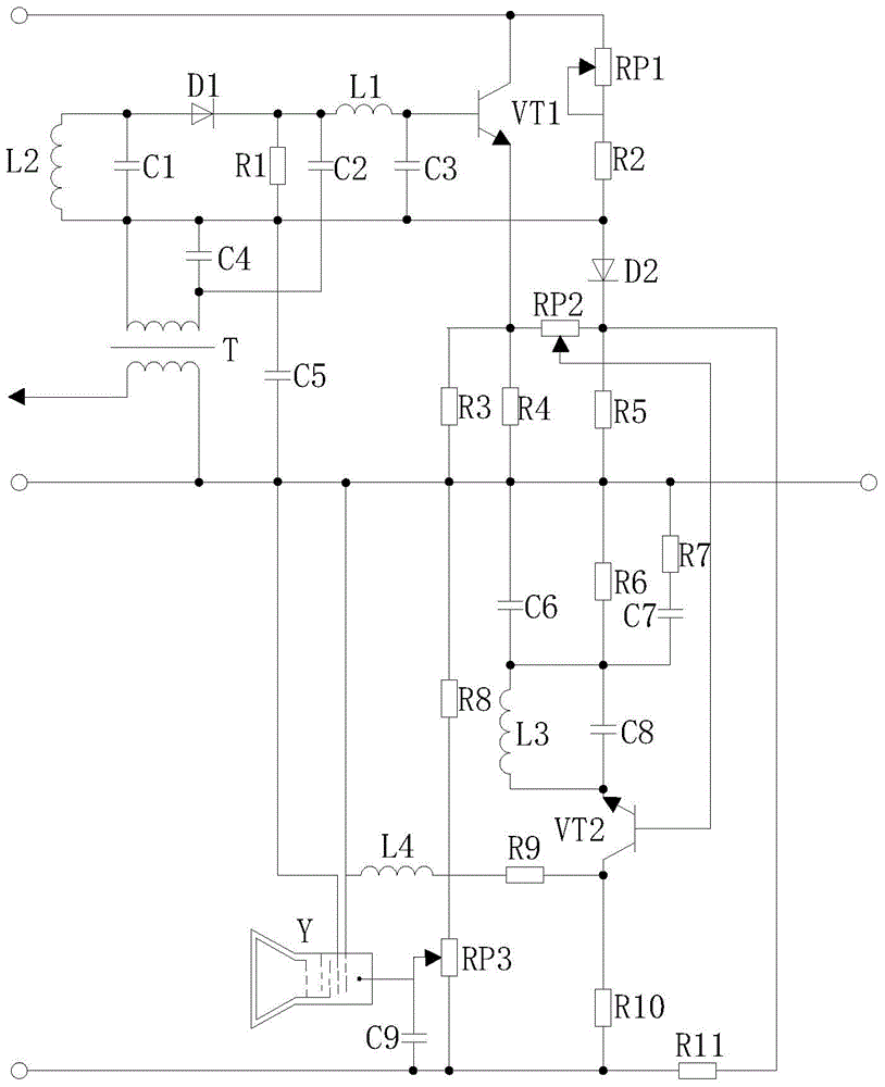
[0010] Such as figure 1 As shown, the present invention is a video amplifier for a video monitoring device, including the first potentiometer RP1 to the third potentiometer RP3, the first triode VT1, the second triode VT2, the first resistors R1 to the tenth A resistor R11, the first inductance coil L1 to the fourth inductance coil L4, the first diode D1, the second diode D2, the first capacitor C1 to the ninth capacitor C9 and the transformer T, the first voltage input terminal is connected to the The collector of the first triode VT1 is connected to the first terminal of the first potentiometer RP1, and the second voltage input terminal is respectively connected to the first terminal of the ninth capacitor C9, the first terminal of the third potentiometer RP3, and the tenth resistor The first end of R10 is connected to the first end of the eleventh resistor R11, the base...


PUM


Abstract

The invention discloses a video amplifier for a video monitoring device. The video amplifier comprises first to third potentiometers, a first triode, a second triode, first to eleventh resistors, first to fourth inductance coils, a first diode, a second diode, first to ninth capacitors and a transformer, wherein a first voltage input end is connected with a collector of the first triode and a first end of the first potentiometer respectively; a second voltage input end is connected with a first end of the ninth capacitor, a first end of the third potentiometer, a first end of the tenth resistor and a first end of the eleventh resistor respectively. The variation amplitude is reduced when the load power of the video amplifier for the video monitoring device varies together with the ray power of a video player, so that videos can be played clearly; the video amplifier is simple in structure and has popularization and usage values.

Description

technical field [0001] The invention relates to an amplifier, in particular to a video amplifier used in a video monitoring device. Background technique [0002] A video amplifier is provided in the video monitoring device to amplify the video signal to enhance the brightness, chroma and synchronous signal of the video. However, when the video transmission distance is relatively long, it is better to use a video cable with a thicker diameter, and at the same time, a video amplifier can be added in the line to enhance the signal strength to achieve the purpose of long-distance transmission. The video amplifier can enhance the brightness, chroma and synchronous signal of the video, but the interference signal in the line will also be amplified. When the ray power in the video playback device and the load power of the traditional video amplifier change at the same time, the magnitude of the change is too large, resulting in the video being too bright or too dark when the video...

Claims


Application Information

Patent Timeline
Patent Type & Authority Applications(China)
IPC IPC(8): H04N5/14
Inventor 郭辉罗彬覃树建
Owner CHENGDU KAIZHI TECH
Learn More