Devices and systems for thrombus treatment

A treatment device and thrombus technology, applied in the field of devices and systems for thrombus treatment, can solve problems such as travel, pulmonary embolism and the like

Active Publication Date: 2015-04-29
WL GORE & ASSOC INC
View PDF8 Cites 9 Cited by
  • Summary
  • Abstract
  • Description
  • Claims
  • Application Information

AI Technical Summary

Problems solved by technology

In the case of DVT treatment, a dislodged thromboembolism may travel to the lung, causing a pulmonary embolism, which can be fatal

Method used


Image

  • Devices and systems for thrombus treatment
  • Devices and systems for thrombus treatment
  • Devices and systems for thrombus treatment

Examples


Embodiment Construction

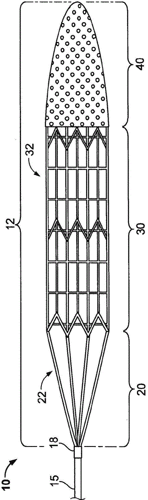
[0056] figure 1 An example embodiment of the thrombus removal device 100 is shown. Such devices can be delivered transdermally and through the patient's vasculature to the site of thrombus, such as neurovascular, cardiovascular, or peripheral venous thrombotic sites. The thrombus removal device 10 can be used in antegrade and retrograde applications.

[0057] The example thrombus removal device 10 generally includes a support wire 15 and a distal device body 12, which includes three (3) main components: (i) tethering assembly 20; (ii) body frame 30; and (iii) ) Filter bag 40. The central collar 18 can couple the tethering assembly 20 to the support wire 15. The body of the distal device can be collapsed so that it can be housed in the catheter lumen for delivery to the thrombus location through the patient's vasculature (e.g., refer to Figure 2D with Figure 2E ). At the thrombus site, the thrombus removal device 10 can be deployed outward from the distal tip of the delivery ...


PUM


Abstract

A thrombus treatment device includes a support wire, a body frame portion that is disposed about an axis defined by the support wire, one or more tethers that each have a first end and a second end, and a filter element extending from the body frame portion. Each of the one or more tethers is attached at its first end to the body frame portion, and at its second end to a collar that couples the second end of each of the multiple tethers to the support wire. When the collar is positioned substantially within a region interior of the body frame portion, a rotational actuation of the support wire causes a swiveling motion of the one or more tethers.

Description

[0001] Cross references to related applications [0002] This application claims the priority of U.S. Provisional Application No. 61 / 683,043 filed on August 14, 2012. The disclosure of the earlier application is considered a part of the disclosure of this application and is incorporated into the disclosure of this application by reference. This application also incorporates by reference the publication of a co-pending application entitled "DEVICES AND SYSTEMS FOR THROMBUS TREATMENT" filed on March 13, 2013 (Agent Case No. MP / 426). Technical field [0003] The present disclosure relates to devices, systems, and methods for treating thrombus. Background technique [0004] Blood clot formation or "thrombosis" is the basis of many serious diseases, such as ischemic stroke, myocardial infarction (heart attack) and deep vein thrombosis (DVT). Blood clots or "thrombi" form inside blood vessels and block the flow of blood through the circulatory system, thereby depriving tissues and orga...

Claims


Application Information

Patent Timeline
Patent Type & Authority Applications(China)
IPC IPC(8): A61B17/3207
CPCA61B17/320725A61F2/013A61B2017/22069A61F2002/018A61B17/221A61M25/00A61B17/320758A61B2017/320716A61B2017/320733A61B2017/2212A61B2017/320004
Inventor E·H·库利N·L·费里德曼E·H·扎卡赖亚斯
Owner WL GORE & ASSOC INC
Why Eureka
Try Eureka