A sequential logic control mechanism

A technology of control mechanism and sequential logic, which is applied to aircraft parts, roofs, transportation and packaging, etc., can solve the problems of low load capacity of the chute, failure to work normally, large space occupation, etc., and achieve light weight, small space occupation, and good stiffness effect

Active Publication Date: 2017-01-18
CHENGDU AIRCRAFT DESIGN INST OF AVIATION IND CORP OF CHINA
View PDF6 Cites 0 Cited by
  • Summary
  • Abstract
  • Description
  • Claims
  • Application Information

AI Technical Summary

Problems solved by technology

The bearing capacity of the chute is not high, it is easy to wear, the positioning accuracy is poor after wear, and the chute is an open mechanism, if any foreign matter falls into it, it may cause the mechanism to be stuck and not work properly
[0006] Since the retractable and locking of the hatch door is realized through many mechanical parts such as connecting rods, sliders, and chute, the above-mentioned structural form takes up a lot of space and is not suitable for some conditions that are particularly sensitive to space.

Method used


Image

  • A sequential logic control mechanism
  • A sequential logic control mechanism
  • A sequential logic control mechanism

Examples


Embodiment Construction

[0042] The present invention will be described in further detail below in conjunction with the accompanying drawings.

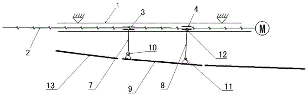
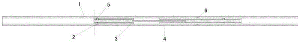
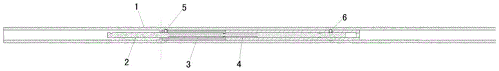
[0043] Please also see Figure 1 to Figure 10 , The control mechanism includes a fixed slide rail 1, a drive shaft 2, a front drive slider 3, a rear drive slider 4, a front ball 5, a rear ball 6, a front cantilever 7, a rear connecting rod 8, and a hatch 9.

[0044] The front driving slider 3 and the rear driving slider 4 are nested on the drive shaft 2 , and the front driving slider 3 and the rear driving slider 4 are nested in the fixed slide rail 1 .

[0045] The upper end of the front cantilever 7 is fixed with the front drive slider 3, and the lower end is connected with the hinge 10 with the front shaft of the cabin door 9.

[0046] Preferably, the upper end of the rear connecting rod 8 is connected with the rear drive slider 4 through a hinge 12 , and the lower end is connected with the rear rotating shaft of the hatch door 9 through a hinge 11 .

[...


PUM


Abstract

The invention belongs to a structural design technology and relates to a time sequence logic control mechanism. The time sequence logic control mechanism comprises a fixed slide rail, a driving shaft, a front driving slider, a rear driving slider, a front ball, a rear ball, a front cantilever, a rear connecting rod and a cabin door. The mechanism achieves logic switch among the closed state, the inward inclination state and the opening state of the cabin door in a narrow and small space and achieves state locking. Compared with the prior art, the number of the parts needed for the mechanism is small, and the mechanism is light, small in occupied space and simple. Compared with the prior art, the mechanism is simple, high in bearing capacity and high in reliability.

Description

technical field [0001] The invention belongs to the structural design technology and relates to a sequential logic control mechanism. Background technique [0002] Among the mechanisms such as doors, skylights, and cover plates that need to be opened and closed by sliding, the most common form is to include one or more movable skylights, slide rails, retractable mechanisms and driving devices, etc., so as to realize the tilting of the skylight, Close or open. [0003] In the Patent Grant No. CN101367327A published by the State Intellectual Property Office of China, in the invention patent titled "Open Roof Structure for Vehicles", the mechanism contains at least three sets of different combinations of slide rails and sliders, which will result in a high The space requirement in the direction increases. Secondly, when the sunroof is tilted, the rear slider moves to the position of the front slider, which makes the force form of the sunroof not good. In the high-speed state, ...

Claims


Application Information

Patent Timeline
Patent Type & Authority Patents(China)
IPC IPC(8): B60J7/02B64C1/14
Inventor 李黎赵服科袁一彬黄建云谷云峰甘学东
Owner CHENGDU AIRCRAFT DESIGN INST OF AVIATION IND CORP OF CHINA
Why Eureka
Try Eureka