Vacuumizing device

A vacuuming device and vacuuming technology, which is applied in the direction of pumping device, vacuum/special atmosphere packaging, transportation and packaging, etc., can solve the problems of inconvenient cleaning, insufficient cleaning and high cost of vacuuming tanks

Inactive Publication Date: 2015-05-06
CHANGXING TIANCHEN MOLD
View PDF6 Cites 5 Cited by
  • Summary
  • Abstract
  • Description
  • Claims
  • Application Information

AI Technical Summary

Problems solved by technology

[0002] The vacuum tank in the existing vacuum device is generally integrally formed to fully ensure its airtightness, but the vacuum tank with this structure is not easy to clean, or the cleaning is not sufficient, and the vacuum tank is easily affected after long-term use. The purity of the material needs to be replaced regularly, and the cost is high

Method used


Image

  • Vacuumizing device
  • Vacuumizing device

Examples


Embodiment Construction

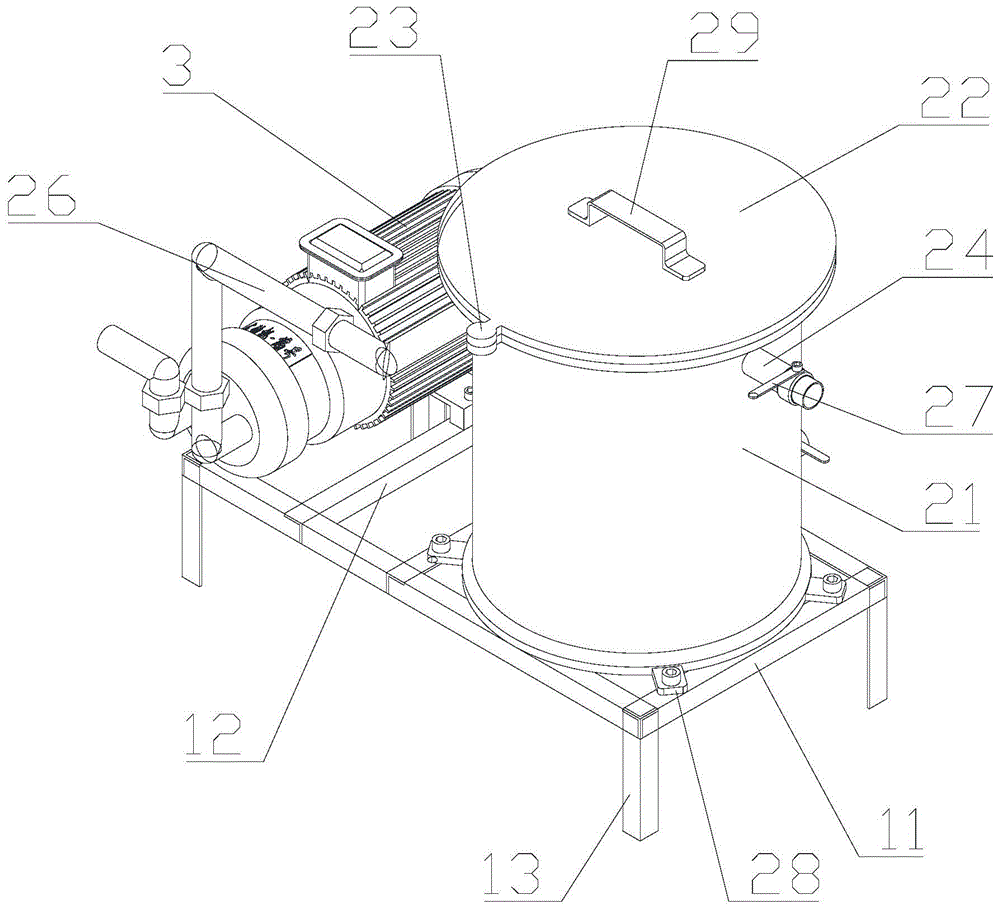
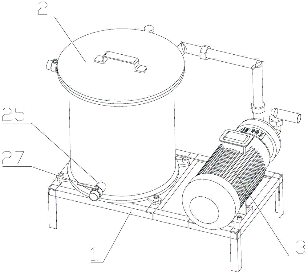
[0014] Such as figure 1 and figure 2 Shown, a kind of vacuum device comprises frame 1, vacuum tank 2 and vacuum pump 3, and vacuum tank and vacuum pump are installed on the frame. Frame comprises rectangular frame 11, connecting rod 12 and support foot 13, and described connecting rod is arranged in rectangular frame and the extending direction of connecting rod and width direction are consistent, and connecting rod divides rectangular frame into smaller rectangular frame, and described supporting leg Set at the right corners of the rectangle. The vacuum tank includes a tank body 21 with an opening and a cover 22 threaded on the tank body for sealing the opening, the tank body and the cover body are respectively provided with a cylindrical calibration part 23, and the cover body When the tank body is screwed until the two calibration parts are completely overlapped, the cover body and the tank body are sealed and fitted. The tank body is provided with a feed pipe 24, a disc...


PUM


Abstract

The invention discloses a vacuumizing device. The vacuumizing device comprises a vacuumizing tank and a vacuumizing pump, wherein the vacuumizing tank comprises a tank body and a cover body, wherein calibration parts are respectively arranged on the tank body and the cover body; when the cover body and the tank body are tightly screwed until the two calibration parts are thoroughly overlapped, the cover body is in sealing fit with the tank body; a feeding pipe, a discharging pipe and a vacuumizing pipe are arranged on the tank body; valves are respectively arranged at parts, on the outer side of the tank body, of the feeding pipe and the discharging pipe; the vacuumizing tank is communicated with the vacuumizing pump through the vacuumizing pipe. When the cover body is rotated until the cover body is tightly screwed and the calibration part of the cover body is thoroughly overlapped with the calibration part of the tank body, the cover body is in thorough sealing fit with the tank body; the gas in the vacuumizing tank is extracted by the vacuumizing pump; then the valve on the discharging pipe is switched off for outputting the material; the cover body can be screwed out for washing the vacuumizing tank after being used; the vacuumizing device is convenient and effective; the vacuumizing tank does not need to be replaced regularly; the cost is reduced; due to the arrangement of the calibration parts, the excessive rotation or insufficient rotation of the cover body can be avoided.

Description

technical field [0001] The invention relates to a vacuum device. Background technique [0002] The vacuum tank in the existing vacuum device is generally integrally formed to fully ensure its airtightness, but the vacuum tank with this structure is not easy to clean, or the cleaning is not sufficient, and the vacuum tank is easily affected after long-term use. The purity of the material needs to be replaced regularly, and the cost is relatively high. Contents of the invention [0003] The problem to be solved by the present invention is to provide a vacuuming device, in which the vacuuming tank has a split structure, which is easy to clean and can be used for a long time under the condition of fully ensuring the sealing, which greatly saves the cost. [0004] In order to solve the above-mentioned technical problems, the present invention adopts the following technical solutions: a vacuum pumping device, comprising a vacuum pump and a vacuum pump, the vacuum pump includes ...

Claims


Application Information

Patent Timeline
Patent Type & Authority Applications(China)
IPC IPC(8): F04B37/14F04B41/02F04B39/10B65D81/20
Inventor 李应泽
Owner CHANGXING TIANCHEN MOLD
Why Eureka
Try Eureka