
Fabricated type cable through-wall fixing device and cable through-wall laying construction method

A fixed device and prefabricated technology, used in cable laying equipment, electrical components, etc., can solve the problems of easily damaged concrete walls, delayed power transmission time, long construction period, etc., to improve laying efficiency, ensure normal operation, The effect of low cost price

Active Publication Date: 2015-05-06
STATE GRID CORP OF CHINA +2
View PDF6 Cites 17 Cited by
  • Summary
  • Abstract
  • Description
  • Claims
  • Application Information

AI Technical Summary

Problems solved by technology

The shortcomings of the above technologies are: due to the need for phased construction, the construction period is long, and in the later construction of the cable through the wall, the concrete wall is easy to be damaged, and the repair is also difficult, which will eventually lead to the delay of the power transmission time point

Method used


Image

  • Fabricated type cable through-wall fixing device and cable through-wall laying construction method
  • Fabricated type cable through-wall fixing device and cable through-wall laying construction method
  • Fabricated type cable through-wall fixing device and cable through-wall laying construction method

Examples


Embodiment Construction

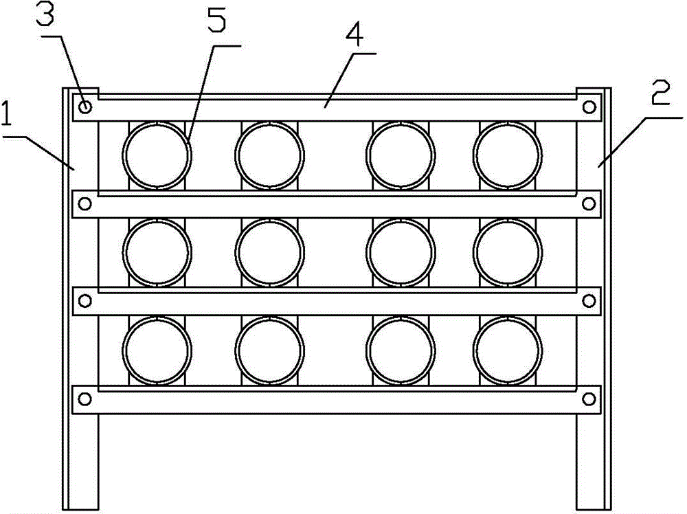
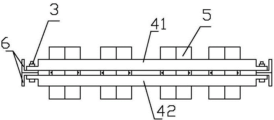
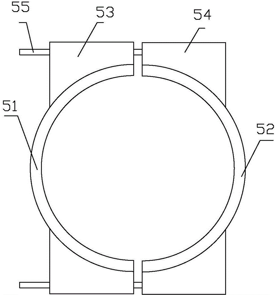
[0021] refer to figure 1 , figure 2 , image 3 Make the invention. The assembled cable wall fixing device includes a left bracket 1 and a right bracket 2, and is characterized in that a cross arm 4 is fixed between the left bracket 1 and the right bracket 2 by bolts 3, and two adjacent cross arms A combination sleeve 5 is provided between the 4.

[0022] The cross-sections of the left bracket 1 and the right bracket 2 are both "T" shaped.

[0023] Both the left bracket 1 and the right bracket 2 are composed of two angle steel bars 6 whose cross sections are at right angles.

[0024] The cross arm 4 is composed of a front cross arm 42 and a rear cross arm 41 arranged in parallel, and is clamped on both sides of the left bracket 1 and the right bracket 2 .

[0025] The front cross arm 42 and the rear cross arm 41 are also made of angle steel bars with a right angle cross section.

[0026] The combined casing 5 is composed of a left semicircular casing 51, a right semicirc...


PUM


Abstract

The invention discloses a fabricated type cable through-wall fixing device and a cable through-wall laying construction method. The fabricated type cable through-wall fixing device comprises a left support and a right support, and is characterized in that cross arms are fixed between the left support and the right support through bolts, and combined sleeves are arranged between every two adjacent cross arms. The method includes the following steps of laying cables in cable channels, fixing the left support and the right support, fixedly arranging one cross arm at the top ends, installing the corresponding combined sleeves on the cables, lifting the four cables in one set, inserting left rib plates and right rib plates on the upper sides of the sleeves into the gaps of the cross arm on the top, fixedly arranging the second cross arm below the set of cables, inserting left rib plates and right rib plates on the lower sides of the combined sleeves into the gaps of the second cross arm, fixing the two ends of the second cross arm to the left support and the right support, repeatedly executing the steps, pouring concrete and completing construction. Construction and installation are easy and convenient, the cable laying efficiency is improved, and the normal running of transformer substations and circuits is ensured.

Description

technical field [0001] The present invention relates to an improvement of wall penetration construction in cable laying, in particular to an assembled cable wall penetration fixing device and a construction method for cable penetration wall laying. The location of the wall opening where cables pass through, such as the exit. Background technique [0002] In the current substation project and high-voltage line distribution project, the work of laying cable through the wall will be carried out, which can not only prevent small animals from damaging the cable, but also play the role of fire prevention for the firewall, and can also be used as a retaining wall to prevent waterlogging Disaster etc. The actual cable laying construction is a multi-phase and sub-item construction project, and the cable cannot be laid at one time, which makes subsequent cable laying more difficult. It is difficult to properly solve the problems of waterproof, fire prevention and small animal preven...

Claims


Application Information

Patent Timeline
Patent Type & Authority Applications(China)
IPC IPC(8): H02G3/22H02G1/06
CPCH02G1/06H02G3/22
Inventor 陈兆强张波刘立倪广魁杨军永赵迎李岩韩凯于志勇王斌斌孟宪民
Owner STATE GRID CORP OF CHINA
Learn More