
Circulating lubricating system with automatic cleaning function

A cyclic lubrication and automatic cleaning technology, applied in sedimentation tanks, chemical instruments and methods, separation methods, etc., can solve the problems of difficult to clean impurities, turbid lubricating liquid, and reducing the lubricating performance of lubricating liquid, so as to reduce the generation of foam, reduce The generation of waste water, the effect of improving lubricating performance

Inactive Publication Date: 2015-05-13
苏闽(张家港)新型金属材料科技有限公司
View PDF5 Cites 6 Cited by
  • Summary
  • Abstract
  • Description
  • Claims
  • Application Information

AI Technical Summary

Problems solved by technology

[0004] The disadvantages of the above-mentioned wet pull cycle lubrication system are: 1. When the impurity-containing lubricating liquid enters the sedimentation tank, due to the excessive return speed of the lubricating liquid, the impurity-containing lubricating liquid will form impact and disturbance in the sedimentation tank, thereby generating a large amount of foam , the foam will float on the surface of the lubricating liquid in the entire sedimentation tank, which will increase the difficulty of cleaning, and the foam will float on the surface of the lubricating liquid with impurities, so that the impurities will slowly settle, and the lubricating liquid in the sedimentation tank will always be Turbidity reduces the lubricating performance of the lubricating fluid, which will lead to broken wires in wet drawing, damage to the surface of steel wires, increased wear and tear of wet drawing dies, etc., which affect product quality; 2. The impurities at the bottom of the sedimentation tank are difficult to clean up, and the impurities are not cleaned up in time It will also cause the lubricating fluid to be turbid, thereby affecting the lubricating performance of the lubricating fluid, and every time the impurities at the bottom of the sedimentation tank are cleaned, the production needs to be stopped, which affects the production efficiency. will pollute the environment

Method used


Image

  • Circulating lubricating system with automatic cleaning function

Examples


Embodiment Construction

[0017] The present invention will be further described in detail below in conjunction with specific embodiments and accompanying drawings.

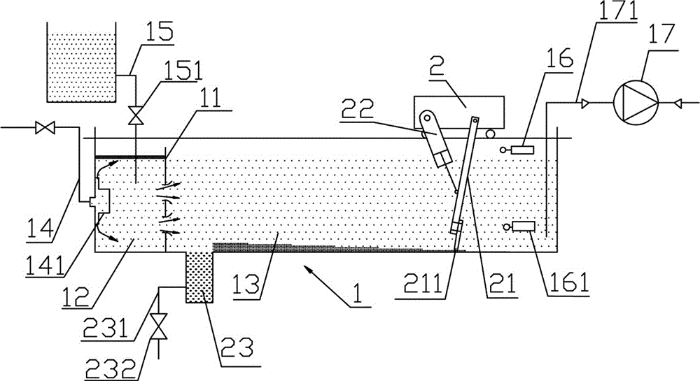
[0018] A circulating lubrication system with automatic cleaning function, such as figure 1 As shown, including a sedimentation tank 1, a foam partition 11 capable of blocking the surface foam of the lubricating liquid is arranged in the sedimentation tank 1, and the foam partition 11 separates the sedimentation tank 1 into a foam isolation zone 12 and an impurity precipitation zone 13, and the impurity precipitation zone The length of 13 is 20~30m. A liquid return pipe 14 is arranged in the foam isolation area 12. The lubricating liquid containing impurities enters the foam isolation area 12 through the liquid return pipe 14, and then enters the impurity precipitation area 13 to precipitate impurities. This setting can The foam is isolated in the foam isolation zone 12, so as not to affect the precipitation of impurities in the impurity p...


PUM

PropertyMeasurementUnit
Lengthaaaaaaaaaa

Abstract

The invention discloses a circulating lubricating system with an automatic cleaning function. The circulating lubricating system comprises a settling pond, wherein a foam separation plate capable of blocking the foam on the surface layer of lubricating liquid is arranged in the settling pond, the settling pond is divided by the foam separation plate into a foam isolation area and an impurity settling area, a return liquid pipe is arranged in the foam isolation area, the lubricating liquid containing impurities enters the foam isolation area by virtue of the return liquid pipe and then enters the impurity settling pond so as to settle impurities, an impurity clearing device capable of clearing the impurities on the bottom of the impurity settling area is arranged in the impurity settling area, and a liquid pumping pipe capable of pumping the clean lubricating liquid is arranged on the rear end of the impurity settling pond. By adopting the circulating lubricating system with the automatic cleaning function, the foam can be reduced and isolated, and the impurities on the bottom of the settling pond can be online cleared.

Description

technical field [0001] The invention relates to a circulating lubricating system with automatic cleaning function capable of circulating and providing clean lubricating fluid. Background technique [0002] In the steel wire production industry, wet drawing refers to the production process in which the steel wire is pulled through between the dies and squeezed by the dies to quickly reach the desired radial size of the steel wire. [0003] Generally, the wet-drawing circulation lubrication system refers to: the lubricating liquid required in the production process of wet-drawing is extracted from the sedimentation tank, and the lubricating liquid containing impurities will return to the sedimentation tank to precipitate impurities after wet-drawing, so that the wet-drawing is continuously reciprocated. The production process provides lubricating fluid. [0004] The disadvantages of the above-mentioned wet pull cycle lubrication system are: 1. When the impurity-containing lub...

Claims


Application Information

Patent Timeline
IPC IPC(8): B21C9/00B01D21/04B01D21/18
Inventor 吴晓玲
Owner 苏闽(张家港)新型金属材料科技有限公司
Learn More