Large angle ejection mechanism for injection molding
An inclined roof mechanism and the technology of inclined roof, which is applied in the field of large inclined roof mechanism for injection molding, can solve the problems of high manufacturing cost of large inclined roof mechanism, and achieve the effects of improving manufacturing convenience, reducing manufacturing cost, and reducing wear
- Summary
- Abstract
- Description
- Claims
- Application Information
AI Technical Summary
Problems solved by technology
Method used
Image
Examples
Embodiment 1
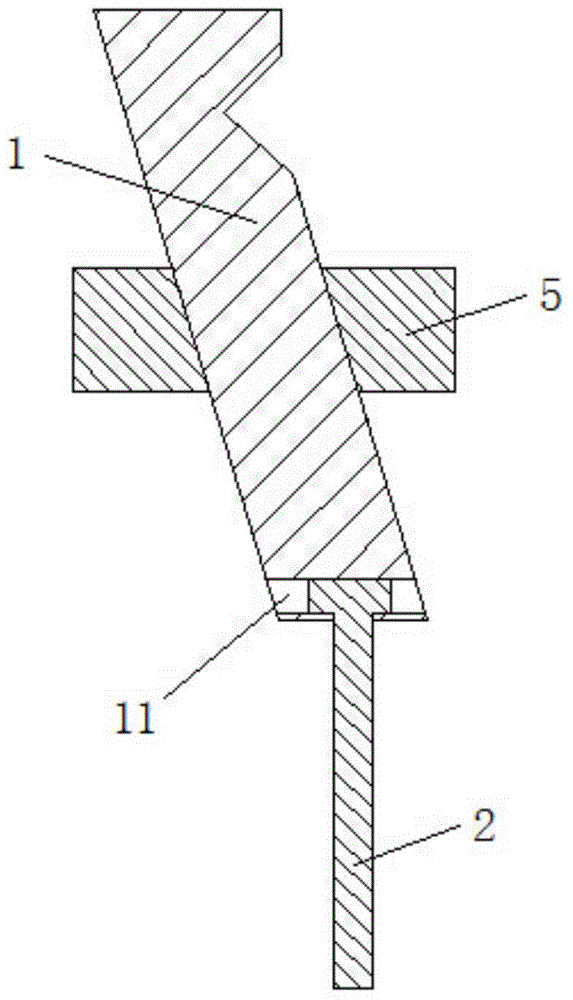
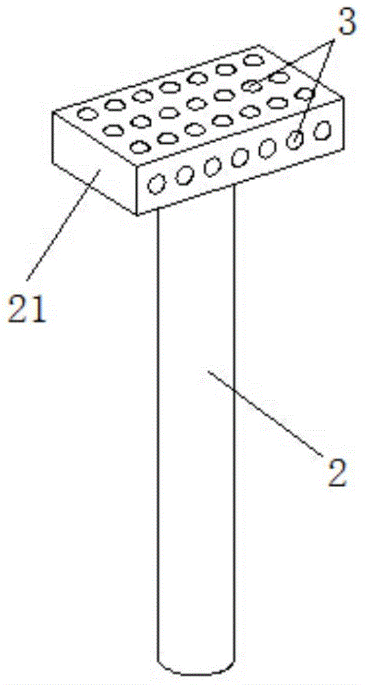
[0015] see figure 1 with figure 2 , The present invention has an inclined top body 1; the bottom end of the inclined top body 1 is provided with a top rod 2; the bottom end of the inclined top body 1 is provided with a sliding groove 11; the top end of the top rod 2 is provided with a slider 21. The sliding block 21 is slidably arranged in the sliding groove 11 of the inclined top body 1; the bottom end of the top rod 2 is fixedly connected with the mounting seat; the extending direction of the sliding groove 11 is horizontal, and the top rod 2 is connected to the sliding groove 11 The extending direction of the groove 11 is vertical.
[0016] The sliding block 21 and the sliding groove 11 are provided with a ball set 3 on the plane where the sliding groove 11 fits; the ball set 3 is rolled and embedded on the sliding block 21, and the exposed surface of the ball set 2 is in contact with the inner wall of the sliding groove 11.
[0017] The inclined roof body 1 is provided with an...
Embodiment 2
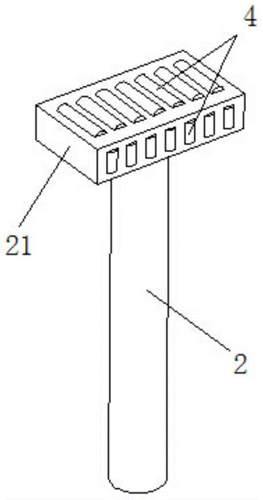
[0019] see figure 1 with image 3 , The sliding block 21 and the sliding groove 11 are provided with a needle roller set 4 on the mating plane; the needle roller set 4 is rolled and embedded on the sliding block 21; the sliding block 21 is on a plane perpendicular to the bottom of the sliding groove 11 The axis of each needle of the needle roller set 4 is parallel to the axis of the ejector pin 2; the axis of each needle of the needle roller set 4 on the plane parallel to the bottom of the sliding groove 11 on the slider 21 is parallel to The axis of the jack 2 is vertical and parallel to the bottom of the sliding groove 11; the exposed surface of the needle roller assembly 4 is in contact with the inner wall of the sliding groove 11. Other technical features are the same as the first embodiment.
PUM
 Abstract
Description
Claims
Application Information
 - R&D
- Intellectual Property
- Life Sciences
- Materials
- Tech Scout
- Unparalleled Data Quality
- Higher Quality Content
- 60% Fewer Hallucinations
Browse by: Latest US Patents, China's latest patents, Technical Efficacy Thesaurus, Application Domain, Technology Topic, Popular Technical Reports.
© 2025 PatSnap. All rights reserved.Legal|Privacy policy|Modern Slavery Act Transparency Statement|Sitemap|About US| Contact US: help@patsnap.com


