Conveniently-assembled LED lamp support and LED lamp with same

A technology of LED lamp bracket and LED lamp bead, which is applied to the parts of lighting device, lighting device, lighting auxiliary device, etc., can solve the problem of affecting the contact between the heat dissipation part and the back of the LED lamp bead, the inability to realize the clamping function, and the lack of bracket materials. Elasticity and other issues, to achieve the effect of reducing product defect rate, simple structure and improving production efficiency

Inactive Publication Date: 2015-05-13
林闽应
View PDF17 Cites 2 Cited by
  • Summary
  • Abstract
  • Description
  • Claims
  • Application Information

AI Technical Summary

Problems solved by technology

However, in the existing structure, these flanges or snap-in mechanisms either cause gaps and affect the contact between the heat dissipation part and the back of the LED lamp bead, or because the flanges or snap-in mechanisms are integrally formed with the bracket The lack of elasticity of the material itself makes it impossible to realize the clamping function. Therefore, the industry has not been able to solve the above problems well.

Method used


Image

  • Conveniently-assembled LED lamp support and LED lamp with same
  • Conveniently-assembled LED lamp support and LED lamp with same
  • Conveniently-assembled LED lamp support and LED lamp with same

Examples


Embodiment 1

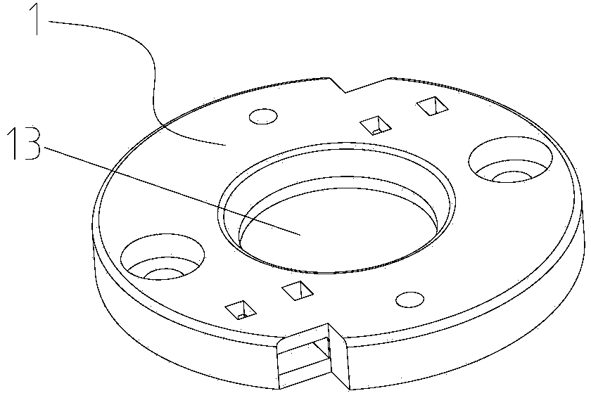
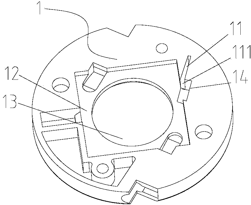
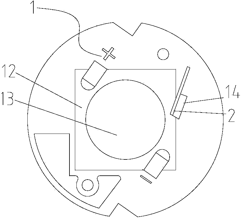
[0031] Such as Figure 1-Figure 5 As shown, in this embodiment, the middle part of the back of the bracket body 1 is an LED lamp bead installation groove 12, and the middle of the LED lamp bead installation groove 12 is a light-transmitting hole 13 for the LED lamp bead 3 to emit light. The LED lamp bead installation groove 12 is rectangular.

[0032] In this embodiment, an installation slot 11 is provided outside the LED lamp bead installation slot 12 , and the installation slot 11 communicates with the inner space of the LED lamp bead installation slot 12 . The installation slot 11 is inserted with a metal shrapnel 2 . An opening is provided between the installation slot 11 and the LED lamp bead installation slot 12, and a notch is also provided on the top.

[0033] In this embodiment, the metal shrapnel 2 is roughly in the shape of a rectangular flat sheet, part of the metal shrapnel 2 is fixed by the installation slot 11, and a part extends from the installation slot 11 ...

Embodiment 2

[0036] Such as Figure 6-Figure 8As shown, in this embodiment, there are two installation slots 11 outside the LED lamp bead installation groove 12 , which are located on the opposite sides of the LED lamp bead 3 . The side of the metal dome 2 can be provided with an elastic joint 21 that spreads out against the side wall of the installation slot 11 to prevent loosening, such as Figure 9 , Figure 10 As shown, after being inserted into the installation slot 11, the elastic engagement portion 21 is in contact with the wall of the installation slot 11 to prevent the metal dome 2 from loosening in reverse. Others are with embodiment 1.

[0037] When assembling the LED lamp including the above-mentioned bracket, first put the back of the bracket body 1 upwards, place the LED lamp bead 3 obliquely into the LED lamp bead installation groove 12, and put pressure on the two metal shrapnels 2 on the two sides respectively. It moves out of the installation space of the LED lamp bead...


PUM


Abstract

The invention discloses a conveniently-assembled LED lamp support comprising a support body with the back provided with an LED bead installation groove. The support body is provided with at least one installation groove position communicated with the internal space of the LED bead installation groove. Metal elastic sheets are inserted into the installation groove position, penetrate the side walls of the LED bead installation groove through the installation groove position to extend to the LED bead installation space, the heads can be pressed to the side of the LED bead, and the width of the metal elastic sheets is not larger than the distance between the bottom of the installation groove position and the back of the assembled LED bead. The support is simple in structure and easy to produce and assemble and is adaptive to batch production; the elastic force of the metal elastic sheets clamps and fixes the LED bead into the groove to prevent the LED bead from loosening or shifting when the support body overturns, the metal elastic sheets are prevented from being higher than the back of the assembled LED bead, the convenience for assembling is guaranteed, the producing efficiency is improved by 10 times of that of an existing structure (1 to 2 seconds are spent on assembling the LED bead), the heat radiation of the LED bead is guaranteed, and the product defective rate is reduced.

Description

technical field [0001] The invention relates to the field of lighting decorations, in particular to an LED lamp bracket. Background technique [0002] Because LED lamps are energy-saving, environmentally friendly and have high brightness, they are increasingly favored by consumers. Existing LED lamps generally include brackets, LED lamp beads and heat dissipation parts that need to be connected and fixed in sequence. [0003] The middle part of the back of the bracket (the side connected to the heat sink) is generally provided with an LED lamp bead installation groove. Since the positive and negative poles of the LED lamp bead must correspond to the positive and negative poles of the power supply, the general operation is to first turn the bracket upside down and install the LED lamp bead in the installation groove with the front facing down. , and then turn over the bracket with the LED light beads to cover the larger heat sink, and then insert screws from the bracket to ...

Claims


Application Information

Patent Timeline
Patent Type & Authority Applications(China)
IPC IPC(8): F21V21/00F21V19/00F21Y101/02
CPCF21V21/00F21V19/004
Inventor 林闽应
Owner 林闽应
Why Eureka
Try Eureka