Multi-hole fuel gas jet flow burner

A gas nozzle, gas technology, applied in the direction of burner, combustion type, combustion method, etc., can solve problems such as combustion instability

Active Publication Date: 2015-05-13
东方电气洁能科技成都有限公司
View PDF4 Cites 8 Cited by
  • Summary
  • Abstract
  • Description
  • Claims
  • Application Information

AI Technical Summary

Problems solved by technology

[0007] The purpose of the present invention is to provide a porous gas jet burner, which has a reasonable structure, can solve the problem of unstable combustion in the process of changing working conditions of the combustion device, can ensure that there is no tempering when the fuel flow is small, and that the fuel flow is large. No fire-off and flame-out, no combustion vibration during the combustion process, increase the combustion intensity as much as possible, and reduce the size of the combustion area

Method used


Image

  • Multi-hole fuel gas jet flow burner
  • Multi-hole fuel gas jet flow burner
  • Multi-hole fuel gas jet flow burner

Examples


Embodiment Construction

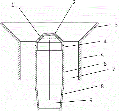
[0034] Such as figure 1 As shown, a porous gas jet burner includes a gas pipeline 6, a gas nozzle 2, an air pipeline 5 and an air pipeline outlet 3, the gas pipeline 6 is connected to the gas nozzle 2, the air pipeline 5 is connected to the air pipeline outlet 3, and the air pipeline 5 is coaxially installed with the gas pipeline 6, the air pipeline 5 is located outside the gas pipeline 6, the gas pipeline 6 is a gas flow channel 9, and the cavity between the air pipeline 5 and the gas pipeline 6 is an air flow channel 7; the gas nozzle 2 Located at the center of the outlet 3 of the air duct.

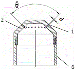
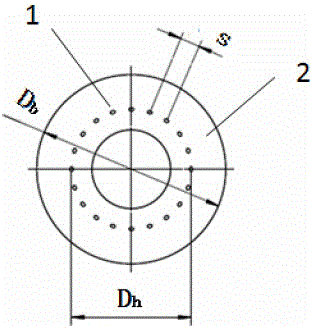
[0035] Such as Figure 2-3 As shown, a circle of fire holes 1 is evenly arranged on the wall of the gas nozzle 2, and the annular ring formed by the fire holes 1 takes the axial centerline of the gas nozzle 2 as the center.

[0036] The structure of the porous gas jet burner needs to meet:

[0037] (1)D h / D b The ratio range is 0.4-0.8, where D h is the annular diameter formed by...


PUM


Abstract

The invention discloses a multi-hole fuel gas jet flow burner. The burner comprises a gas pipeline, a gas nozzle, an air pipeline and an air pipeline outlet, wherein the gas pipeline is a gas flow passageway, a hollow cavity between the air pipeline and the gas pipeline is an air flow passageway, a round of fire holes are evenly formed in the wall of the gas nozzle, an axial centre line of the gas nozzle serves as a circle center of an annular ring formed by the fire holes, and the following formulas: Dh / D b = 0.4-0.8, d / s =1.5-4, theta= 20 degrees-150 degrees are satisfied; the fire holes and intervals are arranged reasonably, and fully co-firing of gas and air can be achieved; multi-hole fuel gas jet flow is injected into incoming flow air in the direction of an included angle formed by an axis of the nozzle and the multi-hole fuel gas jet flow, expansion type flow is adopted to form a negative pressure in a rear side of the gas nozzle, backflow of high temperature smoke is achieved, and flame blowoff and flameout are avoided; air flow can increase negative pressure in the rear side of the gas nozzle, the backflow of the high temperature smoke is facilitated, and flame stabilization is further facilitated; fuel gas jet flow injects into shear layer outside a backflow area, and mixing of the air and flue is facilitated.

Description

technical field [0001] The invention relates to an accessory of a gas combustion device, in particular to a porous gas jet burner. Background technique [0002] The burner is a key part of the gas combustion device, which is commonly found in various combustion-related industrial equipment, such as: boilers, kilns, waste incinerators and gas turbines. A burner with good performance can reasonably organize the mixing of fuel and oxidant, realize safe and stable combustion, and ensure sufficient combustion efficiency and pollutant emission standards. For some special industrial devices, it is also necessary to meet the flexible adjustment requirements of flame length, luminous degree, combustion intensity, combustion temperature and heat load. According to the primary air coefficient, the combustion time can be divided into diffusion combustion, partial premix combustion and complete premix combustion. According to the air supply method, it can be divided into ejection combu...

Claims


Application Information

Patent Timeline
Patent Type & Authority Applications(China)
IPC IPC(8): F23D14/22F23D14/48F23D14/46
CPCF23D14/22F23D14/46F23D14/48
Inventor 唐豪杰万志伟王晓亮吴家桦朱鼎李少华
Owner 东方电气洁能科技成都有限公司
Why Eureka
Try Eureka