

Side-channel pump, and method for operating a side-channel pump
A side channel and channel technology, applied in the field of side channel pumps and running side channel pumps, can solve the problems of small leakage gaps and inability to offset the entry of gas.
- Summary
- Abstract
- Description
- Claims
- Application Information
AI Technical Summary
Problems solved by technology
Method used
Image

Examples
Embodiment Construction
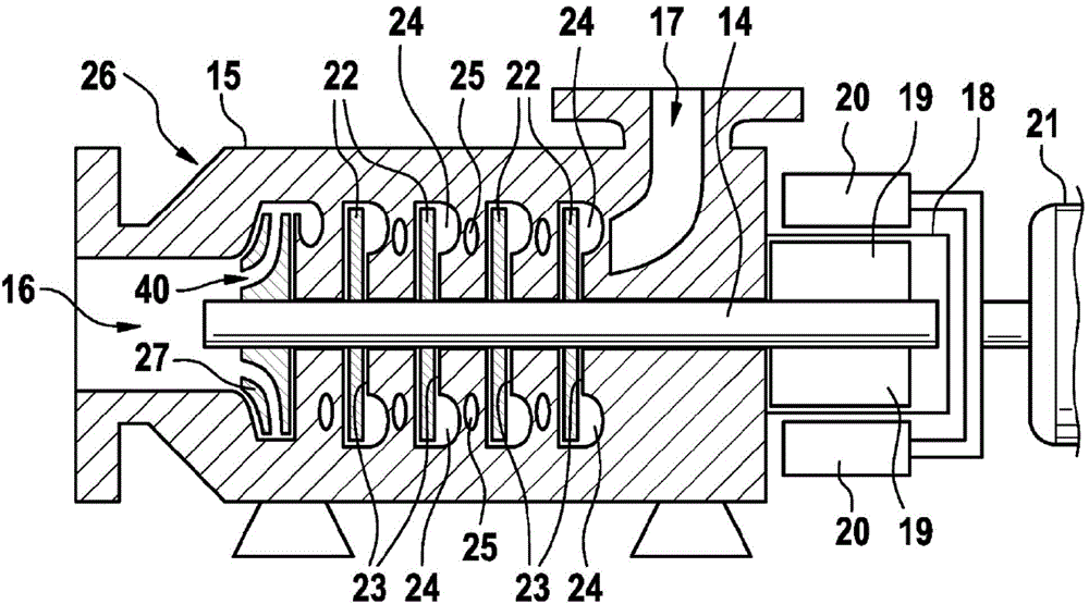
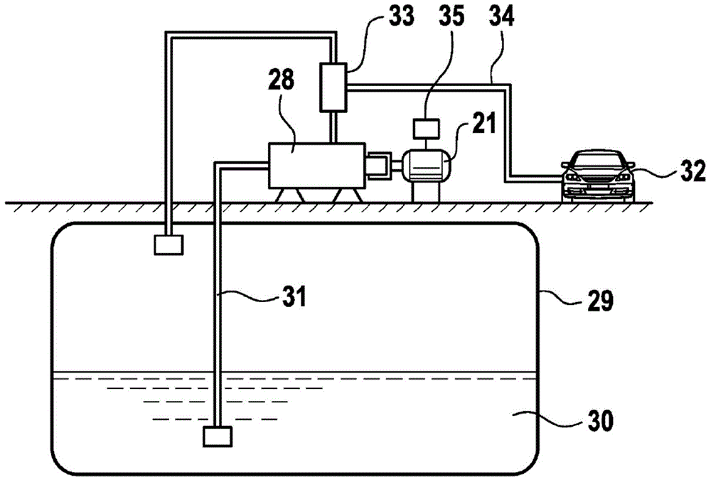
[0026] exist figure 1 In the case of the side channel pump according to the present invention, the rotating shaft 14 is rotatably installed in the pump casing 15 . The pump casing 15 has an inlet hole 16 and an outlet hole 17 , wherein the inlet hole 16 is arranged concentrically with the rotating shaft 14 . The end of the pump casing 15 opposite the inlet hole 16 is designed as a split cage 18 in which the magnet elements 19 connected to the rotating shaft 14 are arranged. A magnet element 19 is arranged outside the split cage 18 , said element being connected to the output shaft of the electric motor 21 . The electric motor 21 has a controller 35 .
[0027] If the electric motor 21 is operated, the magnet element 20 performs a rotational movement about the split cage 18 . Rotation is also applied to the shaft 14 by magnetic transmission, so that it rotates in synchronization with the output shaft of the motor 21 . Since one end of the shaft 14 enters the inlet hole 16 an...
PUM
 Abstract
Description
Claims
Application Information