vehicle floor structure

A vehicle and floor technology, which is applied in the field of floor structure, can solve the problems of adverse effects on the layout of surrounding components, increased weight, and reduced compartment space, and achieves the effects of improving rigidity, increasing bearing load, and restraining bending deformation.

Inactive Publication Date: 2017-07-28
SUZUKI MOTOR CORP
View PDF1 Cites 0 Cited by
  • Summary
  • Abstract
  • Description
  • Claims
  • Application Information

AI Technical Summary

Problems solved by technology

In this case, if the rigidity of the floor is increased by adding other parts, it will adversely affect the layout of the surrounding parts and increase the weight. Not only that, it may also reduce the space in the cabin, so it cannot be called useful. Methods

Method used


Image

  • vehicle floor structure
  • vehicle floor structure
  • vehicle floor structure

Examples


Embodiment Construction

[0026] Hereinafter, the present invention will be described in detail based on the illustrated embodiments.

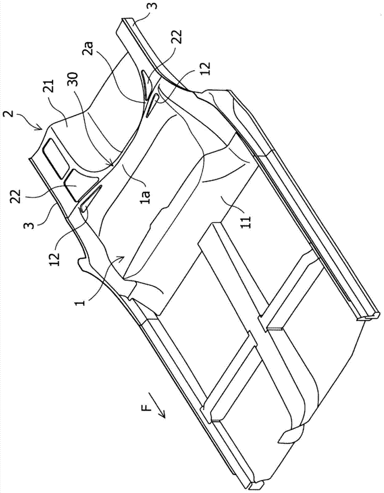
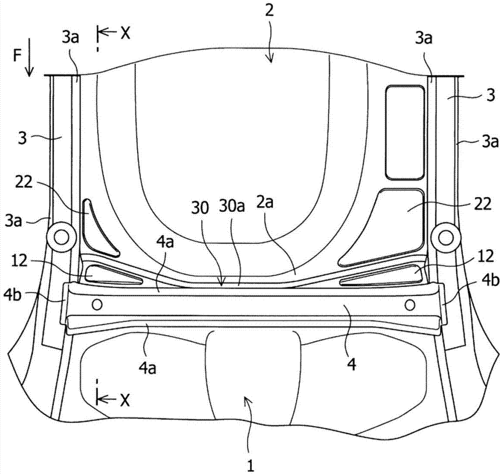
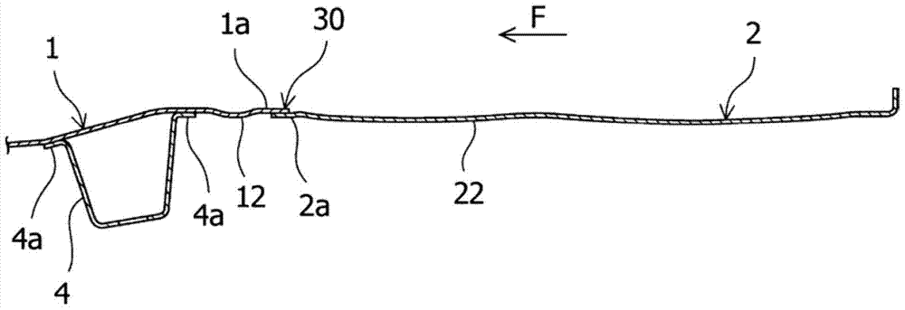
[0027] Figure 1 ~ Figure 4 The floor structure of the vehicle which shows embodiment of this invention. and, in Figure 1 ~ Figure 4 In , the arrow F direction indicates the front of the vehicle.

[0028] Such as Figure 1 ~ Figure 4 As shown, the floor structure of the vehicle according to the embodiment of the present invention has a front floor (combined by combining relatively independent front outer panels and center panels) 1 and a rear floor 2 arranged along the front-rear direction of the vehicle. That is, in the floor structure of the present embodiment, the rear end 1a of the front floor 1 extending from the vehicle front to the vehicle rear and the front end 2a of the rear floor 2 extending from the vehicle rear to the vehicle front are joined by spot welding in a state where they overlap up and down. Together, the joining surface part 30 is formed in t...


PUM


Abstract

The invention provides a vehicle floor structure that even when the rear end of the floor panel receives by a force acting from the rear of the vehicle forth impact load an in-vehicle acting upward load, can prevent that associated surface portions as a starting point for a high jumping of a rear end serve a floor panel in order to prevent a deformation, which additionally can reduce vibrations in a base plate surface. In the vehicle floor structure, wherein a front floor panel (1), extending from the front to the rear of a vehicle, is connected to a rear floor panel (2), which extends to the front of a vehicle from the stern, is provided between a rear end (1a) of the front floor panel (1) and a front end (2a) of the rear floor panel (2) is formed in the vehicle transverse direction of a joined surface portion (30), and the joined surface portion (30) is arranged so that it is inclined from a center in the vehicle transverse direction portion (30a) in the direction of the vehicle rear to the vehicle sides.

Description

technical field [0001] The present invention relates to a floor structure of a vehicle, and particularly relates to a structure of a floor constituting a vehicle floor portion. Background technique [0002] Conventionally, a floor constituting a floor portion of a vehicle such as an automobile is formed of a plurality of panels, and the panels are joined to each other by welding or the like. Such a floor is required to withstand impact loads, suppress vibrations received by the vehicle body, and the like. In this case, if the rigidity of the floor is increased by adding other parts, it will adversely affect the layout of the surrounding parts and increase the weight. Not only that, it may also reduce the space in the cabin, so it cannot be called useful. Methods. [0003] Therefore, in the conventional floor structure, the performance of suppressing the vibration received by the vehicle body may be improved by increasing the rigidity of the floor instead of adding other co...

Claims


Application Information

Patent Timeline
Patent Type & Authority Patents(China)
IPC IPC(8): B62D25/20
CPCB62D25/20B62D25/087B62D25/2027
Inventor 细见祐介
Owner SUZUKI MOTOR CORP
Why Eureka
Try Eureka