A method for rapid and directional growth of carbon nanofibers on the surface of carbon fibers

A carbon nanofiber, directional growth technology, used in carbon fiber, fiber processing, textiles and papermaking, etc., can solve the problems of low cohesion and low bonding strength, and achieve the effects of low equipment investment, high safety and energy saving

Inactive Publication Date: 2016-10-26
EAST CHINA JIAOTONG UNIVERSITY
View PDF2 Cites 0 Cited by
  • Summary
  • Abstract
  • Description
  • Claims
  • Application Information

AI Technical Summary

Problems solved by technology

Due to the chemical inertness of the surface, the carbon fiber without surface treatment has very little bonding force with the matrix carbon, so that the bonding strength with the matrix is ​​low, and the traditional C / C composite material has low strength, toughness, conductivity, Thermal conductivity and other mechanical or physical properties, there is a large anisotropy

Method used


Image

  • A method for rapid and directional growth of carbon nanofibers on the surface of carbon fibers
  • A method for rapid and directional growth of carbon nanofibers on the surface of carbon fibers

Examples


Embodiment 1

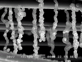
[0025] The untreated carbon fiber (take T700-12K carbon fiber as an example, the fiber length is 10cm, the mass is m=0.0086g), electrified along the length direction, with acetylene as the carbon source gas, nitrogen as the carrier gas, C 2 h 2 =40mL / min, N 2 =60mL / min, the initial deposition voltage is 25V (the selection of the voltage value is different due to the K number and length of the carbon fiber, and the initial power per unit volume is 5*10 9 W·m -3 left or right, select a suitable voltage value), electrify in a steady state, deposit 10-60min, preferably deposit 10-30min, the SEM appearance of pyrolytic carbon deposited on the surface of carbon fiber is as follows figure 2 As shown, the length of oriented pyrolytic carbon can reach 50 μm. As the deposition progresses, the voltage remains constant under constant voltage, and the current decreases continuously, that is, the heating power decreases continuously.

Embodiment 2

[0027] Dry the carbon fiber with the same length and weight as in Example 1 after degumming, take this sample as the cathode, take nickel sulfate as the electroplating solution (200g / L), room temperature, current intensity is 100mA, electroplating 3min, after deionization After soaking in water, cleaning and drying, deposit in the chemical vapor deposition furnace of the present invention, the deposition initial voltage is 25V, and the gas flow rate is C during the deposition process. 2 h 2 =10ml / min, N 2 =200ml / min, the deposition time is 0.5h, and the weight gain of carbon fiber after deposition is 148%.

Embodiment 3

[0029] Dry the carbon fiber with the same length and weight as in Example 1 after degumming, use this sample as the cathode, take nickel sulfate as the electroplating solution (200g / L), room temperature, the current intensity is 100mA, electroplating for 3min, after deionization After soaking in water, cleaning and drying, deposit in the chemical vapor deposition furnace of the present invention, the deposition initial voltage is 25V, and the gas flow rate is C during the deposition process. 2 h2 =30ml / min, N 2 =200ml / min, the deposition time is 0.5h, and the weight gain of carbon fiber after deposition is 276%.


PUM

PropertyMeasurementUnit
lengthaaaaaaaaaa

Abstract

The invention provides a method for growing carbon nanofibers rapidly and directionally on the surface of a carbon fiber. The method is characterized in that the carbon fiber is arranged in deposition equipment and is directly electrified for heating due to the excellent conductivity of the carbon fiber, the temperature of the carbon fiber is improved by heat generated by the carbon fiber, carbon source gas is cracked and the deposition purpose is achieved. According to the method, the equipment investment is low, the operation is simple, the deposition speed can be adjusted freely, the deposition efficiency is improved, energy is saved, and the directional carbon nanofibers can rapidly grow without additional measures.

Description

technical field [0001] The invention relates to a new material preparation method, in particular to a method for rapid and directional growth of carbon nanofibers on the surface of carbon fibers. Background technique [0002] Carbon fibers have extremely high specific strength and specific modulus, excellent electrical and thermal conductivity, corrosion resistance, and good high temperature resistance in reducing atmospheres, and are widely used as reinforcement (toughening) phases of composite materials. The excellent performance of C / C composites depends on the structure and properties of carbon fibers, the structure and properties of matrix carbon, and the interfacial bonding state of carbon fibers and matrix carbon. During the preparation of C / C composites, matrix carbon initially nucleates and grows on the surface of carbon fibers and forms a bonding interface. The surface state of carbon fibers directly affects the bonding state of matrix carbon initially deposited on...

Claims


Application Information

Patent Timeline
Patent Type & Authority Patents(China)
IPC IPC(8): D06M11/74C04B35/83D06M101/40
Inventor 徐先锋柴灵芝
Owner EAST CHINA JIAOTONG UNIVERSITY
Why Eureka
Try Eureka