A sucker device

A technology of suction cups and limit devices, which is applied in the direction of suction cups, connecting components, mechanical equipment, etc., can solve the problems of inconvenient removal of suction cups, repeated use of suction cups, and inconvenient position adjustment, so as to achieve easy removal of suction cups, easy reuse and The effect of adjusting the position

Active Publication Date: 2017-05-10
TUNBOW GRP
View PDF10 Cites 0 Cited by
  • Summary
  • Abstract
  • Description
  • Claims
  • Application Information

AI Technical Summary

Problems solved by technology

[0003] In the prior art, once the suction cup is adsorbed to the contact surface, it is very firm, and it is difficult to quickly inject air into the negative pressure chamber between the suction cup and the contact surface when it is removed, which is inconvenient to remove the suction cup. Inconvenient to use and position adjustment

Method used


Image

  • A sucker device
  • A sucker device
  • A sucker device

Examples


Embodiment Construction

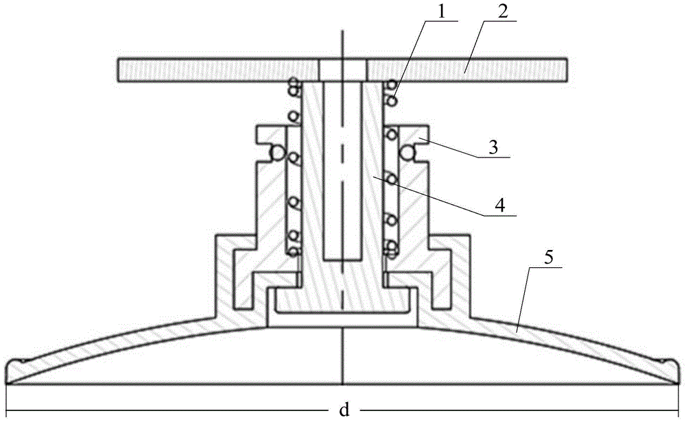
[0026] The invention provides a suction cup device to achieve the purpose of making it easy to be removed from the contact surface, thereby facilitating the repeated use and position adjustment of the suction cup.

[0027] The following will clearly and completely describe the technical solutions in the embodiments of the present invention with reference to the accompanying drawings in the embodiments of the present invention. Obviously, the described embodiments are only some, not all, embodiments of the present invention. Based on the embodiments of the present invention, all other embodiments obtained by persons of ordinary skill in the art without making creative efforts belong to the protection scope of the present invention.

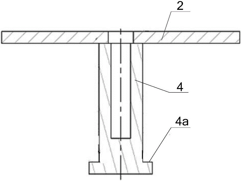
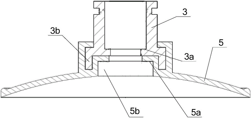
[0028] see Figure 1-Figure 3 , figure 1 Schematic diagram of the structure of the sucker device provided by the embodiment of the present invention; figure 2 Schematic diagram of the structure of the push rod connected with the counterweight in...


PUM


Abstract

The invention discloses a suction cup device which comprises a suction cup body, a pushing rod and a limiting device. The suction cup body comprises a suction cup portion and a skeleton which is connected with the suction cup portion and is coaxial with the suction cup portion. A cavity penetrating through the suction cup portion and the skeleton is formed along the axis of the suction cup body. The pushing rod is arranged in the cavity in a slidable mode. A first step surface which is used for being matched with the suction surface of the suction cup portion and is opposite to the end face of the first end of the pushing rod is arranged at the first end of the pushing rod. The second end of the pushing rod penetrates through the cavity, stretches out from one side of the skeleton and is connected with a balancing weight. The limiting device is arranged between the suction cup body and the balancing weight and used for jacking the balancing weight and enabling the first step surface to be in tight fit with the suction surface. When the suction cup device is in use, the balancing weight vibrates or swings through vibration and moves downwards by overcoming the acting force of the limiting device, then the first step surface of the pushing rod is pushed to be disengaged from the suction surface, the portion between the suction surface and a contact surface is rapidly filled with air, and the purposes that a suction cup is conveniently taken down, the suction cup can be repeatedly used conveniently and the position is adjusted are achieved.

Description

technical field [0001] The invention relates to the technical field of small household appliances, in particular to a suction cup device. Background technique [0002] A suction cup is a tool that uses the difference in atmospheric pressure between the inside and outside to absorb or grab objects, usually in the shape of a round disc with a depression in the middle. [0003] In the prior art, once the suction cup is adsorbed to the contact surface, it is very firm, and it is difficult to quickly inject air into the negative pressure chamber between the suction cup and the contact surface when it is removed, which is inconvenient to remove the suction cup. Use and position adjustment have brought inconvenience. [0004] Therefore, how to provide a suction cup that can be easily removed from the contact surface, thereby facilitating the repeated use and position adjustment of the suction cup, has become an important technical problem to be solved urgently by those skilled in ...

Claims


Application Information

Patent Timeline
Patent Type & Authority Patents(China)
IPC IPC(8): F16B47/00
CPCF16B47/00
Inventor 蔡自光
Owner TUNBOW GRP
Why Eureka
Try Eureka