A defrosting system for air source heat pump

An air source heat pump, one-way technology, used in lighting and heating equipment, damage protection, refrigeration components, etc., can solve the problems of indoor temperature drop, long defrosting time, lag, etc. frost effect

Active Publication Date: 2017-02-22
XI AN JIAOTONG UNIV
View PDF7 Cites 0 Cited by
  • Summary
  • Abstract
  • Description
  • Claims
  • Application Information

AI Technical Summary

Problems solved by technology

When the heat pump air conditioner adopts the reverse cycle defrosting method, the system will absorb heat from the room during the defrosting process, resulting in a decrease in the indoor temperature, which affects the indoor thermal comfort
On the other hand, when switching to heating mode after defrosting, since the surface temperature of the indoor heat exchanger as an evaporator is still very low, the hot air blown by the air conditioner will also lag behind, which also reduces the thermal comfort of the room
The hot gas bypass defrosting method does not need to absorb indoor heat and avoids the phenomenon of blowing cold air during defrosting, but because the heat required for system defrosting in hot gas bypass defrosting comes from the input power of the compressor, so The relatively long defrosting time will also cause the indoor temperature to drop, which also affects the indoor thermal comfort

Method used


Image

  • A defrosting system for air source heat pump
  • A defrosting system for air source heat pump
  • A defrosting system for air source heat pump

Examples


Embodiment 1

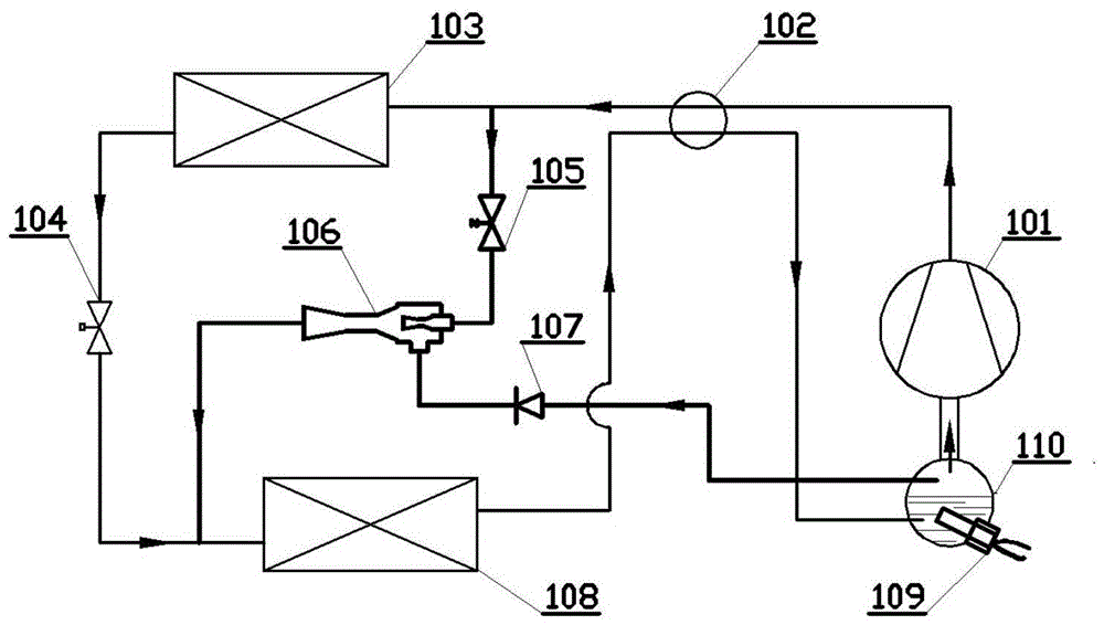
[0027] Such as figure 1 As shown, for the defrosting system of the air source heat pump, the outlet of the compressor 101 is connected with the inlet of the four-way reversing valve 102; The outlet of the indoor heat exchanger 103 is connected to the inlet of the outdoor heat exchanger 108 through the throttling device 104, and the outlet of the outdoor heat exchanger 108 is connected to the compressor 101 through the four-way reversing valve 102. The attached gas-liquid separator is connected; the gas-liquid separator 110 gas outlet of the compressor 101 is divided into two paths, one path is connected with the suction port of the compressor 101, and the other path passes through the one-way throttle valve 107 and the ejector 106 The injected refrigerant inlet is connected; the refrigerant outlet of the ejector 106 is connected with the outdoor heat exchanger 108 inlet; the gas-liquid separator 110 carried by the compressor 101 has an electric heating rod 109 .

[0028] The ...

Embodiment 2

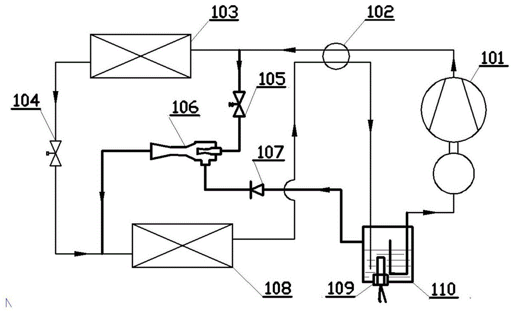
[0031] Such as figure 2As shown, for the defrosting system of the air source heat pump, the outlet of the compressor 101 is connected with the inlet of the four-way reversing valve 102; The outlet of the indoor heat exchanger 103 is connected to the inlet of the outdoor heat exchanger 108 through the throttling device 104, and the outlet of the outdoor heat exchanger 108 is connected to the compressor 101 through the four-way reversing valve 102. The attached gas-liquid separator is connected; the gas outlet of the newly added gas-liquid separator 110 is divided into two paths, one path is connected with the suction port of the compressor 101, and the other path passes through the one-way throttle valve 107 and the ejector 106. The refrigerant inlet of the ejector 106 is connected with the inlet of the outdoor heat exchanger 108; the gas-liquid separator 110 is heated by the electric heating rod 109 inserted therein.

[0032] The high-temperature and high-pressure refrigeran...

Embodiment 3

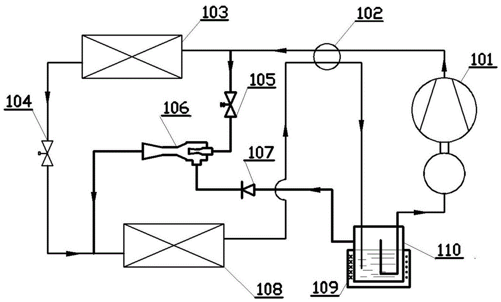
[0035] Such as image 3 As shown, the gas-liquid separator 110 in this embodiment is heated by an electric heating wire wound on the surface of the gas-liquid separator 110 , and the others are the same as in Embodiment 2.


PUM


Abstract

A defrosting system for air source heat pumps. The outlet of the compressor is connected to the inlet of the four-way reversing valve; The outlet of the indoor heat exchanger is connected to the inlet of the outdoor heat exchanger through a throttling device, and the outlet of the outdoor heat exchanger is connected to the gas-liquid separator through a four-way reversing valve; the gas outlet of the gas-liquid separator is divided into two , one way is connected to the suction port of the compressor, and the other way is connected to the injected refrigerant inlet of the ejector through the one-way throttle valve; the refrigerant outlet of the ejector is connected to the inlet of the outdoor heat exchanger; since most compressor exhaust The air still enters the indoor heat exchanger to realize the normal operation of the heat pump circuit and provide heat for the room, avoiding the reduction of indoor thermal comfort. In addition, since the gas-liquid separator with electric heating can increase the defrosting heat supply, it can significantly reduce the defrosting time, which also ensures the indoor thermal comfort requirements.

Description

technical field [0001] The invention belongs to the technical field of refrigeration and air conditioning, and in particular relates to a defrosting system for an air source heat pump. Background technique [0002] With the continuous progress of society and the continuous development of science and technology, people are more and more concerned about the earth on which we live, and most countries in the world have fully realized the importance of the environment to our human development. All countries are taking active and effective measures to improve the environment and reduce pollution. Among them, the most important and urgent problem is the energy problem. In order to solve the energy problem fundamentally, besides finding new energy sources, energy saving is the key and the most direct and effective important measure at present. In recent years, through hard work, people have achieved remarkable results in energy-saving technology research and product development. A...

Claims


Application Information

Patent Timeline
Patent Type & Authority Patents(China)
IPC IPC(8): F25B47/02
CPCF25B47/022F25B41/22F25B41/30
Inventor 鱼剑琳李云翔晏刚
Owner XI AN JIAOTONG UNIV
Why Eureka
Try Eureka