
Device and method for measuring atmospheric transmissivity by optical radiation measurement instrument

A technology for atmospheric transmittance and radiation measurement, applied in transmittance measurement and other directions, which can solve problems such as reliability verification and inconsistency of response spectrum.

Inactive Publication Date: 2015-05-20
姜志富
View PDF9 Cites 6 Cited by
  • Summary
  • Abstract
  • Description
  • Claims
  • Application Information

AI Technical Summary

Problems solved by technology

[0004] Since the parameters for calculating atmospheric transmittance in the prior art are obtained indirectly, it is limited to the integrity and accuracy of atmospheric parameter measurement equipment to obtain atmospheric parameters, and other equipment that directly obtains atmospheric transmittance. The reliability of the atmospheric transmittance obtained by using the existing technology to correct the radiation of the measured target for the optical radiation measuring instrument needs to be verified, and the data still needs to be further corrected.

Method used


Image

  • Device and method for measuring atmospheric transmissivity by optical radiation measurement instrument
  • Device and method for measuring atmospheric transmissivity by optical radiation measurement instrument
  • Device and method for measuring atmospheric transmissivity by optical radiation measurement instrument

Examples


Embodiment Construction

[0036] It should be noted that, in the case of no conflict, the embodiments in the present application and the features in the embodiments can be combined with each other. The present invention will be described in detail below with reference to the accompanying drawings and examples.

[0037] In order to enable those skilled in the art to better understand the solutions of the present invention, the technical solutions in the embodiments of the present invention will be clearly and completely described below in conjunction with the drawings in the embodiments of the present invention. Obviously, the described embodiments are only Some, but not all, embodiments of the invention. The components of the embodiments of the invention generally described and illustrated in the figures herein may be arranged and designed in a variety of different configurations. Accordingly, the following detailed description of the embodiments of the invention provided in the accompanying drawings ...


PUM


Abstract

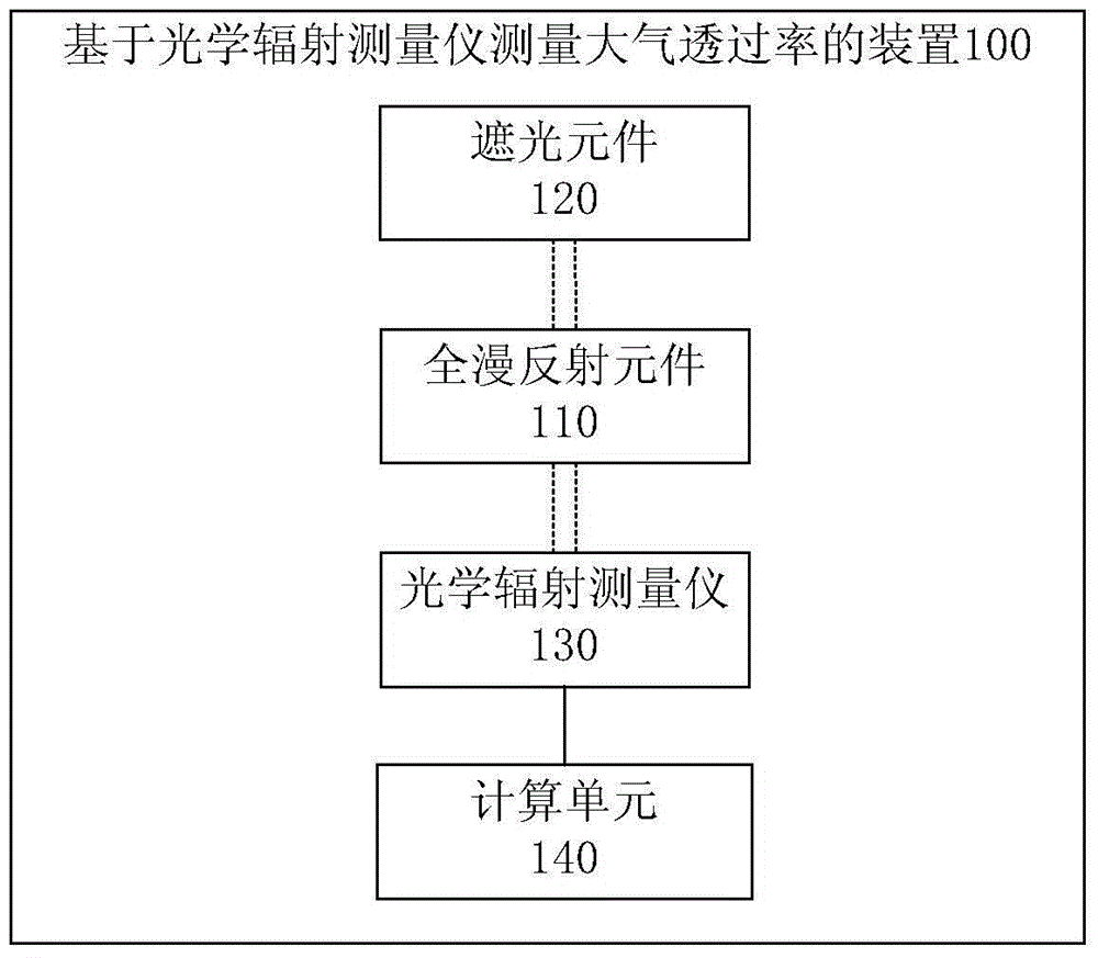
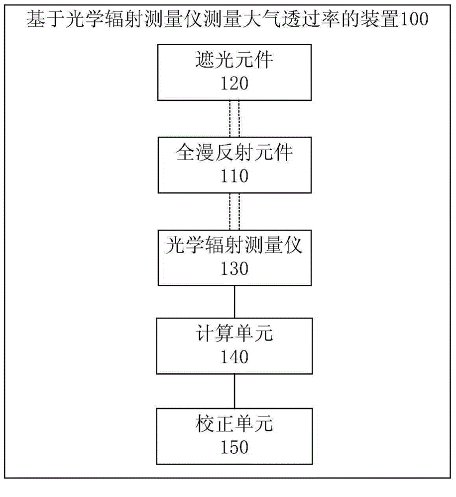
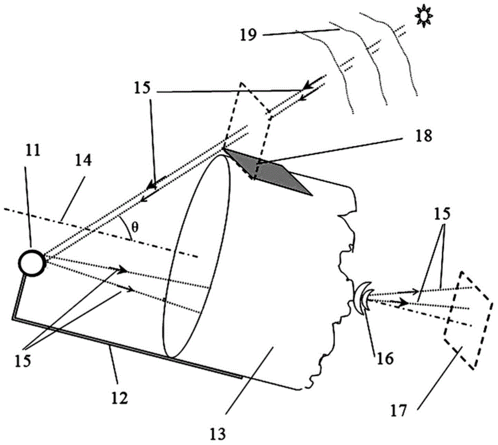
The invention provides a device and a method for measuring the atmospheric transmissivity by an optical radiation measurement instrument. The device comprises a total diffuse reflection element, a shading element, the optical radiation measurement instrument and a computing element, wherein the total diffuse reflection element is used for carrying out diffuse reflection on sun light according to the preset angle so as to enable the sun light to be reflected into the optical radiation measurement instrument; the shading element is capable of keeping out the sun light irradiating the total diffuse reflection element when being arranged at a preset position; the optical radiation measurement instrument is used for measuring the total diffuse reflection element to acquire first response data containing total diffuse reflection sun light, and second response data which does not contain the total diffuse reflection sun light; the computing element is used for calculating the response difference between the first response data and the second response data; the whole layer atmospheric transmissivity at the response spectrum section of the optical radiation measurement instrument on the current measurement path can be obtained according to the response difference and the response data known in advance of the total diffuse reflection sun light positioned outside the atmospheric layer. The device and the method aim at accurately obtaining the whole layer atmospheric transmissivity at the response spectrum section of the optical radiation measurement instrument on the measurement path formed by the sun and the measuring device.

Description

technical field [0001] The invention relates to the fields of optical radiation measurement and atmospheric measurement, in particular to a device and method for measuring atmospheric transmittance based on an optical radiation measuring instrument. Background technique [0002] Optical measurements using optical radiometers are commonly used. When an optical radiometer measures visible light photometry and infrared radiation of a distant target, it is necessary to know the atmospheric transmittance of the response spectrum of the optical radiometer on the measurement path to correct the attenuation effect of the atmosphere on the radiation of the measured target. [0003] In the prior art, the atmospheric optical parameters are usually obtained by auxiliary atmospheric parameter measurement equipment, and then the obtained atmospheric optical parameters are input into the atmospheric transmission calculation software, and the atmospheric transmission calculation software ob...

Claims


Application Information

Patent Timeline
IPC IPC(8): G01N21/59
Inventor 姜志富李满良左亚林吴亚丽马峰孟凡胜杜芳麻纪庵王琳郭毅
Owner 姜志富
Learn More